Electric circuits miscellaneous
- Consider the following circuit :
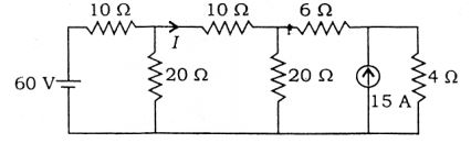
What is the current I in the above circuit?
-
View Hint View Answer Discuss in Forum
Using Thevenin’s theorem, we have

Since the two voltages are equal and in opposition, therefore I = 0.Correct Option: A
Using Thevenin’s theorem, we have
Since the two voltages are equal and in opposition, therefore I = 0.
- In the network shown in the given figure, if the voltage V at the time considered is 20 V, then
dV at that time will be dt 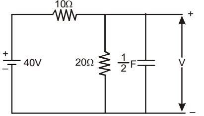
-
View Hint View Answer Discuss in Forum
Given: V = 20 V
∴ Current through 20 ohm resistance = 20 = 1 A 20
Voltage across 10 ohm resistor = 40 – 20 = 20 V
Then current through the capacitor = 2 – 1 = 1 A.∴ C dV = 1 dV A dt 2 dt ⇒ dV = 2 V / s. dt
Correct Option: B
Given: V = 20 V
∴ Current through 20 ohm resistance = 20 = 1 A 20
Voltage across 10 ohm resistor = 40 – 20 = 20 V
Then current through the capacitor = 2 – 1 = 1 A.∴ C dV = 1 dV A dt 2 dt ⇒ dV = 2 V / s. dt
- After closing the switch‘S’ at t = 0, the current i (t) at any instant ‘t’ in the network shown in the given figure will be
-
View Hint View Answer Discuss in Forum
It can be certified by checking the value of the current at t = 0+ , and at t = ∞ which should be zero and 10/1 = 10 A respectively.
It is an R-L circuit∴ i(t) = Vdc [1 - e(– R / L)t] R
Correct Option: D
It can be certified by checking the value of the current at t = 0+ , and at t = ∞ which should be zero and 10/1 = 10 A respectively.
It is an R-L circuit∴ i(t) = Vdc [1 - e(– R / L)t] R
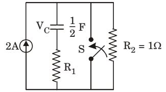
- The circuit shown in the given figure is steady-state with switch ‘S’ open. The switch is closed at t = 0. The values of vc (0+) and vc (∞) will be respectively
-
View Hint View Answer Discuss in Forum
When switchs had been open, the current of 2 A flows through R2 alone. Thus voltage 2 V, and since there is no current in branch 1, the voltage acoss the capacitor is also 2V.
∴ vc (0) = 2
Since after the switching action, voltage across the capacitor cannot change instantaneously,
∴ vc (∞) = vc (0) = 2V.
After the switch is closed and steady state condition reached, the entire current of 2A passes through the closed switch and voltage across the capacitor becomes zero.Correct Option: A
When switchs had been open, the current of 2 A flows through R2 alone. Thus voltage 2 V, and since there is no current in branch 1, the voltage acoss the capacitor is also 2V.
∴ vc (0) = 2
Since after the switching action, voltage across the capacitor cannot change instantaneously,
∴ vc (∞) = vc (0) = 2V.
After the switch is closed and steady state condition reached, the entire current of 2A passes through the closed switch and voltage across the capacitor becomes zero.
- In the circuit shown in the given, the switch S is open for a long time and closed at t = 0.
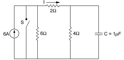
The value I at t = 0+ is
-
View Hint View Answer Discuss in Forum
Voltage across capacitor prior to closing of switch
= 6 × 4 = 12 V 2
Immediately after closing of the switch S, the source current is all diverted into the ‘short’and capacitor furnishes a current of 12 = 6 A in the 2-ohm resistor. 2
The direction is opposite to the marked one.
∴ I = – 6A.Correct Option: A
Voltage across capacitor prior to closing of switch
= 6 × 4 = 12 V 2
Immediately after closing of the switch S, the source current is all diverted into the ‘short’and capacitor furnishes a current of 12 = 6 A in the 2-ohm resistor. 2
The direction is opposite to the marked one.
∴ I = – 6A.

