Electric circuits miscellaneous
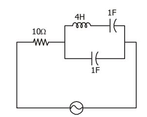
- The circuit shown in the given figure in resonates at
-
View Hint View Answer Discuss in Forum
Input impedance of the circuit,
Z = 10 + 
1 || 
4jω + 1 

jω jω 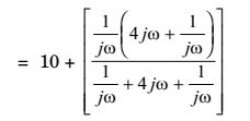
= 10 + [1 - 4ω2] jω[2 - 4ω2] Correct Option: B
Input impedance of the circuit,
Z = 10 + 1 || 4jω + 1 jω jω = 10 + [1 - 4ω2] jω[2 - 4ω2]
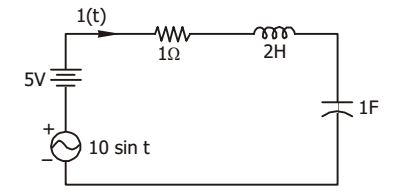
- For the circuit show in the (given figure) i(t) under steady state is
-
View Hint View Answer Discuss in Forum
d.c. voltage 5V would encounter an open circuit in the capacitor and hence the current is 0.
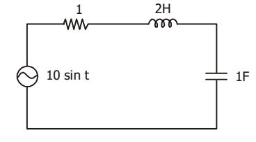
For a.c , i(t) = 10 sin t 1 + j2 + 1 j = 10 sin t = 10 sin (t - 45°) 1 + j √2
= 7.07 sin (t – 45°)
Correct Option: D
d.c. voltage 5V would encounter an open circuit in the capacitor and hence the current is 0.
For a.c , i(t) = 10 sin t 1 + j2 + 1 j = 10 sin t = 10 sin (t - 45°) 1 + j √2
= 7.07 sin (t – 45°)
- Switch S in the given figure is closed at t = 0. If v2 (0) = 10 V and vg (0) = 0 V respectively, voltage across the capacitors in steady state will be

-
View Hint View Answer Discuss in Forum
NA
Correct Option: D
NA
- In the given figure, the switch was closed for a long time before opening at t = 0. The voltage Vx at t = 0+ is
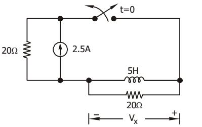
-
View Hint View Answer Discuss in Forum
At t = 0+ , the circuit will be as shown below.
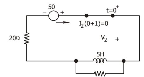
I L (0+) = 0
Then Vi = – 50 VCorrect Option: C
At t = 0+ , the circuit will be as shown below.
I L (0+) = 0
Then Vi = – 50 V
- In the circuit of given figure, assume that the diodes are ideal and meter is an average indicating ammeter. The ammeter will read

-
View Hint View Answer Discuss in Forum
The meter will read during positive half for halfwave rectifier.
Vav = Vm = 4 = 0.4 mA. πR π10K π
Correct Option: D
The meter will read during positive half for halfwave rectifier.
Vav = Vm = 4 = 0.4 mA. πR π10K π

