Electric circuits miscellaneous
- Divergence of the vector field V (x, y, z) = – (x cos xy + y) i + (y cos xy) j + (sin z2 + x2 + y2) k is
-
View Hint View Answer Discuss in Forum
V (x, y, z) = – (x cos xy + y) i + (y cos xy) j + (sin z2 + x 2 + y 2) k
Divergence = ∇ .V = ∂Vx + ∂Vy + ∂Vz ∂x ∂y ∂z
= – cos xy + x (sin xy) (y) + cos xy – y (sin xy) x + 2z cos z2 = 2z cos z2
Correct Option: A
V (x, y, z) = – (x cos xy + y) i + (y cos xy) j + (sin z2 + x 2 + y 2) k
Divergence = ∇ .V = ∂Vx + ∂Vy + ∂Vz ∂x ∂y ∂z
= – cos xy + x (sin xy) (y) + cos xy – y (sin xy) x + 2z cos z2 = 2z cos z2
- A solid sphere made of insulating material has a radius R and has a total charge Q distributed uniformly in its volume. What is the magnitude of the electric field intensity, E, at a distance r (0 < r < R) inside the sphere?
-
View Hint View Answer Discuss in Forum
By Gauss's theorem
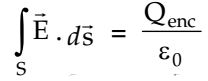
where, Qenc = charge enclosed in radius r
or E(4πr2) = Qr3 R3 or E = Qr 4πε0R3 Correct Option: A
By Gauss's theorem
where, Qenc = charge enclosed in radius ror E(4πr2) = Qr3 R3 or E = Qr 4πε0R3
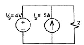
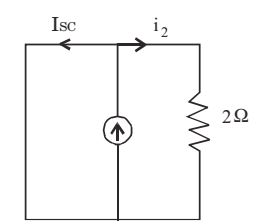
- For the circuit shown below, find out the current flowing through the 2 Ω resistance. Also identify the changes to be made to double the current through the 2 Ω resistance.
-
View Hint View Answer Discuss in Forum
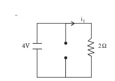
By super position, only voltage sourcei1 = 4 = 2 amp 2
only current source i2 = 2 - I SC = 2 – 2 = 0
&there; Total current, i = i1 + i2 = 2 amp
For current to double, Put Vin = 8V, as current source has no effect while connecting it across voltage source.&there; i = i 1 + i 2 = 8 + 0 = 4 amp 2 Correct Option: B
By super position, only voltage sourcei1 = 4 = 2 amp 2
only current source i2 = 2 - I SC = 2 – 2 = 0
&there; Total current, i = i1 + i2 = 2 amp
For current to double, Put Vin = 8V, as current source has no effect while connecting it across voltage source.&there; i = i 1 + i 2 = 8 + 0 = 4 amp 2
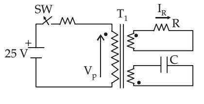
- In the figure given below, transformer T1 has two secondaries, all three windings having the same number of turns and with polarities as indicated. One secondary is shorted by a 10 Ω resistor R, and the other by a 15 μF capacitor. The swit ch SW is opened (t = 0) when the capacitor is charged to 5 V with the left plate as positive. At t = 0+ the voltage VP and current IR are
-
View Hint View Answer Discuss in Forum
At t = 0+, re-drawing the circuit as,
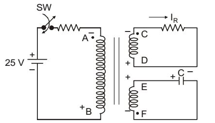
Using dot-convention, VEF = VE - VF = 5
VA has negative polarity as VF has also the same VC has negative polarity as VA has also the same. Since the turns ratio are same, therefore,
VEF = (– VAB) = (– VCD) = 5 volts
⇒ VCD = – 5volts.and IR = VCD = - 0.5 A R Correct Option: D
At t = 0+, re-drawing the circuit as,
Using dot-convention, VEF = VE - VF = 5
VA has negative polarity as VF has also the same VC has negative polarity as VA has also the same. Since the turns ratio are same, therefore,
VEF = (– VAB) = (– VCD) = 5 volts
⇒ VCD = – 5volts.and IR = VCD = - 0.5 A R
- In the circuit shown in figure given below, switch SW1 is initially CLOSED and SW2 is OPEN. The inductor L carries a current of 10 A and the capacitor is charged to 10 V with polarities as indicated. SW2 is initially CLOSED at t = 0 – and SW1 is OPENED at t = 0. The current through C and the voltage across L at t = 0 + is

-
View Hint View Answer Discuss in Forum
The circuit at t = 0 + is drawn as,
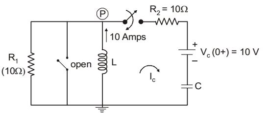
Using KCL at mode P,Vp - 10 + Vp - 10 = 0 10 10
⇒ Vp = 55 volts.and Ic = Vp - Vc = 55 - 10 = 4.5 Amps 10 10
Correct Option: D
The circuit at t = 0 + is drawn as,
Using KCL at mode P,Vp - 10 + Vp - 10 = 0 10 10
⇒ Vp = 55 volts.and Ic = Vp - Vc = 55 - 10 = 4.5 Amps 10 10

