Electric circuits miscellaneous
- In the circuit shown in the given figure, if the switch is closed as t = 0, then the voltage v(0+) and its derivative
 will be respectively
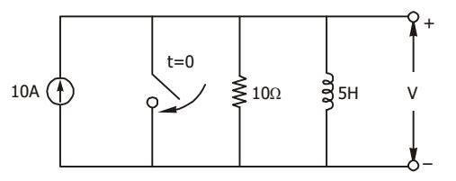
-
View Hint View Answer Discuss in Forum
Here V = 100 volts
∴ 10 = 1 ∫ υdt + V L R
Differentiating,0 = V + dυ × V L dt R ⇒ dυ = - V R = - 200 V/s dt L
Correct Option: D
Here V = 100 volts
∴ 10 = 1 ∫ υdt + V L R
Differentiating,0 = V + dυ × V L dt R ⇒ dυ = - V R = - 200 V/s dt L
- A current shown in the figure passes through a pure inductance at 3 mH. The instantaneous power in watts during 0 < t < 2 ms is

-
View Hint View Answer Discuss in Forum
Instantaneous power, p = vi
For the interval 0 < t < 2,i = 10 × 103 t (tns) 2 v = L di = 3 × 10-3 × 10 × 103 dt 2
∴ p = 75,000 t
Correct Option: C
Instantaneous power, p = vi
For the interval 0 < t < 2,i = 10 × 103 t (tns) 2 v = L di = 3 × 10-3 × 10 × 103 dt 2
∴ p = 75,000 t
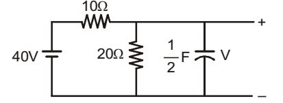
- In the network shown in the given figure, if the voltage V at the time considered is 20 V, then dV/ dt at that time will be
-
View Hint View Answer Discuss in Forum
Given: V = 20 V
Current through 20 ohm resistance = 20 = 1 amp 20
Voltage across 10 ohm resistor = 40 – 20 = 20 V
Current through the capacitor = 2 – 1 = 1 amp∴ C dv = 1 dv = 1 amp dt 2 dt ⇒ dv = 2 V / s dt
Correct Option: B
Given: V = 20 V
Current through 20 ohm resistance = 20 = 1 amp 20
Voltage across 10 ohm resistor = 40 – 20 = 20 V
Current through the capacitor = 2 – 1 = 1 amp∴ C dv = 1 dv = 1 amp dt 2 dt ⇒ dv = 2 V / s dt
- The phase angle of the current I with respect to the voltage V1 in the circuit shown in the figure is

-
View Hint View Answer Discuss in Forum
Net voltage applied to the circuit is 200 ∠0° V
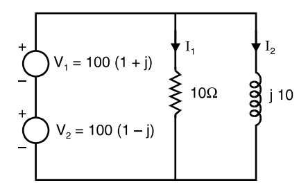
I1 = 200∠0° = 20∠0° = 20 10.0 I2 = 200∠0° = 20∠90° = -j20 10∠90°
∴ I = I1 + I2 = 20(1 – j) = 20 √2 ∠ 45°
Voltage,V1 = 100 (1 + j) = 100 √2 ∠ 45°
Required phase angle = – 45° – 45° = – 90°Correct Option: D
Net voltage applied to the circuit is 200 ∠0° V
I1 = 200∠0° = 20∠0° = 20 10.0 I2 = 200∠0° = 20∠90° = -j20 10∠90°
∴ I = I1 + I2 = 20(1 – j) = 20 √2 ∠ 45°
Voltage,V1 = 100 (1 + j) = 100 √2 ∠ 45°
Required phase angle = – 45° – 45° = – 90°
- A load that has a resistance of 10 ohms is to be connected to a supply that has a constant voltage of 120 volts. If it is desired that the currrent to the load be varied from 3 to 5 amperes, what are the resistance and the current rating of the series rheostat that permit this variation?
-
View Hint View Answer Discuss in Forum
The 10 ohms load when connected to 120 V supply will take a current
110 = 12 A 10
without rheostat in the circuit.
Since it is desired to restrict the current flow through the load at 3 to 5 amperes, therefore voltage drop in the load = 3 × 10 = 30 volts at 3 amperes, and
= 5 × 10 = 50 volts at 5 amperes.
When voltage drop across the load is 30 V, then voltage drop in the rheostat must be = 120 – 30 = 90 volts.
Since same curent flows through the rheostat, resistance of the rheostat must be= 90 = 30 ohms 3
When voltage drop across the load is 50 V, voltage drop in the rheostat must be = 120 – 50 = 70 volts.
Since same current flows through the rheostat, resistance of the rheostat must be= 70 = 14 ohms 5
Thus rating of rheostat must be 30 ohms and 5 amperes.
Correct Option: A
The 10 ohms load when connected to 120 V supply will take a current
110 = 12 A 10
without rheostat in the circuit.
Since it is desired to restrict the current flow through the load at 3 to 5 amperes, therefore voltage drop in the load = 3 × 10 = 30 volts at 3 amperes, and
= 5 × 10 = 50 volts at 5 amperes.
When voltage drop across the load is 30 V, then voltage drop in the rheostat must be = 120 – 30 = 90 volts.
Since same curent flows through the rheostat, resistance of the rheostat must be= 90 = 30 ohms 3
When voltage drop across the load is 50 V, voltage drop in the rheostat must be = 120 – 50 = 70 volts.
Since same current flows through the rheostat, resistance of the rheostat must be= 70 = 14 ohms 5
Thus rating of rheostat must be 30 ohms and 5 amperes.

