Electric circuits miscellaneous
- The switch in the circuit has been closed for a long time. It is opened at t = 0. At t = 0+, the current through the 1 μF capacitor is

-
View Hint View Answer Discuss in Forum
Circuit at t = 0– (at steady state)
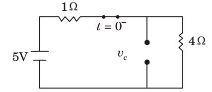
Initial voltage, Vc (0–) = 4 × 5 = 4 V 1 + 4
Circuit at t = 0+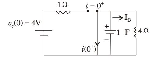
ic(0+) = IB = 4 = 1 amp 4 i = Vc e-t / RC R
Correct Option: B
Circuit at t = 0– (at steady state)
Initial voltage, Vc (0–) = 4 × 5 = 4 V 1 + 4
Circuit at t = 0+ic(0+) = IB = 4 = 1 amp 4 i = Vc e-t / RC R
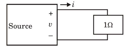
- As shown in the figure given below, a 1Ω resistance is connected across a source that has a load line v + i = 100. The current through the resistance is
-
View Hint View Answer Discuss in Forum
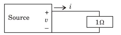
Load line : v + i = 100
From figure, we have
v = 1 × i = i
⇒ v = i
∴ i + i = 100
⇒ i = 50 ACorrect Option: B
Load line : v + i = 100
From figure, we have
v = 1 × i = i
⇒ v = i
∴ i + i = 100
⇒ i = 50 A
- A wattmeter is connected as shown in the figure given below. The wattmeter reads

-
View Hint View Answer Discuss in Forum
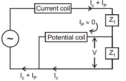
Since potential coil draws negligible current, IP ≈ 0 and current through Z1 and Z2 will be same.
Then, wattmeter will read power consumed by Z2, P = IC .V where V is potential across Z2.Correct Option: D
Since potential coil draws negligible current, IP ≈ 0 and current through Z1 and Z2 will be same.
Then, wattmeter will read power consumed by Z2, P = IC .V where V is potential across Z2.
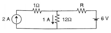
- If 12 Ω resistor draws a current of 1 A as shown in the figure given below, the value of resistance R is
-
View Hint View Answer Discuss in Forum
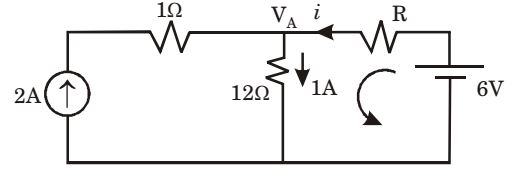
VA = 12
i = 1 – 2 = – 1 amp.
By KVL, 6 – iR – 12 × 1 = 0
⇒ iR = – 6⇒ R = -6 = 6 Ω (-1)
Correct Option: B
VA = 12
i = 1 – 2 = – 1 amp.
By KVL, 6 – iR – 12 × 1 = 0
⇒ iR = – 6⇒ R = -6 = 6 Ω (-1)
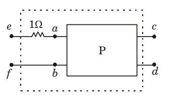
- The two-port network P shown in the figure has ports 1 and 2, denoted by terminals (a, b) and (c, d) respectively. It has an impedance matrix Z with parameters denoted by zij . A 1 Ω resistor is connected in series with the network at port 1 as shown in the figure. The impedance matrix of the modified two-port networ k (shown as a dashed box) is
-
View Hint View Answer Discuss in Forum
Case 1

V1 = Z11 i 1 + Z12 i 2
V2 = Z21 i 1 + Z22 i2
Case 2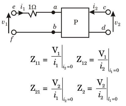
Equivalent circuits
For case 1 : Z11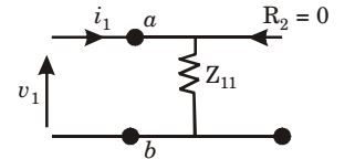
For case 2 :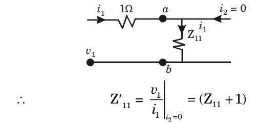
For case 1 :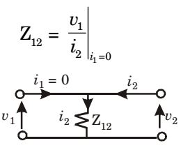
For case 2 :
Z21 for case 1 :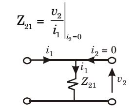
For case 2 :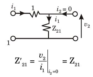
Z22 for case 1 :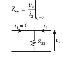
For case 2 :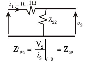
∴ New impedance matrix,Z' = 
Z11 + 1 Z12 
Z21 Z22
Correct Option: C
Case 1
V1 = Z11 i 1 + Z12 i 2
V2 = Z21 i 1 + Z22 i2
Case 2
Equivalent circuits
For case 1 : Z11
For case 2 :
For case 1 :
For case 2 :
Z21 for case 1 :
For case 2 :
Z22 for case 1 :
For case 2 :
∴ New impedance matrix,Z' = Z11 + 1 Z12 Z21 Z22

