Electric circuits miscellaneous
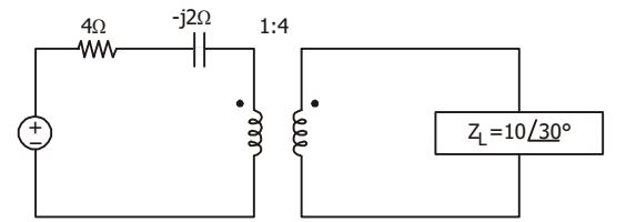
- The impedance seen by the source in the given circuit is
-
View Hint View Answer Discuss in Forum
Z'L = 10 ∠ 30 
1 
2 4
= (0.54 + j0.31) Ω
Total impedance = (4.54 – j 1.69) Ω.Correct Option: C
Z'L = 10 ∠ 30 1 2 4
= (0.54 + j0.31) Ω
Total impedance = (4.54 – j 1.69) Ω.
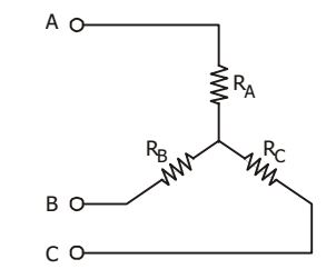
- Consider star network shown in the given figure. The resistance between terminals A and B with C open is 6 Ω, between terminals B and C with A open is 11 Ω, and between terminals C and A with B open is 9 Ω. Then
-
View Hint View Answer Discuss in Forum
Given : RA + RB = 6 with C open
RB + RC = 11 with A open
RC + RA = 9∴ RA + RB + RC = 26 = 13 2
⇒ RA = 2 Ω
Correct Option: B
Given : RA + RB = 6 with C open
RB + RC = 11 with A open
RC + RA = 9∴ RA + RB + RC = 26 = 13 2
⇒ RA = 2 Ω
- Current i(t), through a 10 Ω resistor in series with an inductance is given by i(t) = 3 + 4sin (100t + 45°) + 4sin (300 t + 60°) A RMS value of the current and power dissipated in the circuit respectively are
-
View Hint View Answer Discuss in Forum
i = 3+ 4 sin (1000 + 45°) + 4 sin (300 + 60°) amp
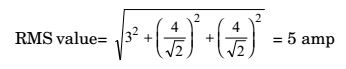
Power = i2 R(RMS)
= 25 × 10 = 250 WCorrect Option: C
i = 3+ 4 sin (1000 + 45°) + 4 sin (300 + 60°) amp
Power = i2 R(RMS)
= 25 × 10 = 250 W
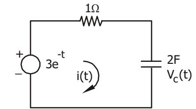
- A circuit consisting of a 1Ω resistor and a 2 F capacitor in series is excited from a voltage source with the voltage expressed as 3e – 4, as shown in the given figure. If i(0– ) and Vc (0– ) both are zero, then values of i(0+) and i(∞) will be respectively
-
View Hint View Answer Discuss in Forum
I(s) R + 1 = 3 Cs s + 1 ⇒ I(s) = 3Cs = 6s (s + 1)(RCs + 1) (s + 1)(2s + 1) Then , i(t) = Z-1 I(s) = Z-1 3s (s + 1){s + (1 / 2)} 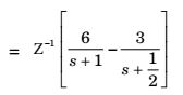
i (t) = 6e– t – 3e– t / 2
∴ i (∞) = 3A, I(0) = 0
Correct Option: C
I(s) R + 1 = 3 Cs s + 1 ⇒ I(s) = 3Cs = 6s (s + 1)(RCs + 1) (s + 1)(2s + 1) Then , i(t) = Z-1 I(s) = Z-1 3s (s + 1){s + (1 / 2)}
i (t) = 6e– t – 3e– t / 2
∴ i (∞) = 3A, I(0) = 0
- Viewed from the terminal AB, following circuit shown in the figure can be reduced to an equivalent circuit of a single voltage source in series with a single resistor with which of the following parameters?

-
View Hint View Answer Discuss in Forum
Applying Thevenin’s theorem
Req = 6 Ω | | 4 Ω = 2.4 ΩVab = 10 - 6 15 = 1 V 10
Correct Option: B
Applying Thevenin’s theorem
Req = 6 Ω | | 4 Ω = 2.4 ΩVab = 10 - 6 15 = 1 V 10

