Electric circuits miscellaneous
-
With the usual notations, a two-port resistive network satisfies the condition A = D = 3 B = 4 C 2 3
z11 of the network is
-
View Hint View Answer Discuss in Forum
Z11 = A = 4 C 4
Correct Option: B
Z11 = A = 4 C 4
- A two-port network is defined by the relations I1 = 2V1 + V2, I2 = 2V1 + 3V2 Then z12 is
-
View Hint View Answer Discuss in Forum
From the equations,
I1 = 2V1 + (I2 - 2V1) 3 ⇒ V1 = 3I1 - I2 4 ∴ Z12 = 1 Ω 4
Correct Option: D
From the equations,
I1 = 2V1 + (I2 - 2V1) 3 ⇒ V1 = 3I1 - I2 4 ∴ Z12 = 1 Ω 4
- An ideal transformer has turns ratio of 2 : 1. Considering high voltage side as port 1 and low voltage side as port 2, then transmission line parameters of transformer will be
-
View Hint View Answer Discuss in Forum
V1 = I1 = N1 = 2 V2 I2 N2 1
⇒ V1 = 2V2
I 1 = 0.5 I2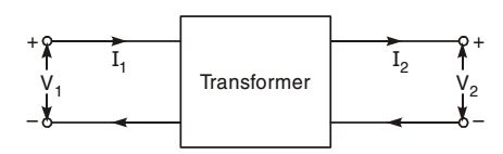
In matrix form,
V1 
= 2 0 V2 I1 0 -0.5 I2
Correct Option: C
V1 = I1 = N1 = 2 V2 I2 N2 1
⇒ V1 = 2V2
I 1 = 0.5 I2
In matrix form,V1 = 2 0 V2 I1 0 -0.5 I2
-
In a passive two-port network, the open-circuit impedance matrix is 10 2 5 2
If input port is interchanged with the output port, then open-circuit impedance matrix will be
-
View Hint View Answer Discuss in Forum
The port-equations are
V1 = 10 I 1 + 2I 2 ....(i)
V2 = 2I 1 + 5 I2 ....(ii)
Rewriting equations (i) and (ii) as
V2 = 5 I2 + 2I1 ....(iii)
V1 = 2 I2 + 10 I1 ....(iv)
Writing in matrix formV2 = 5 2 I2 V1 2 10 I1
Correct Option: B
The port-equations are
V1 = 10 I 1 + 2I 2 ....(i)
V2 = 2I 1 + 5 I2 ....(ii)
Rewriting equations (i) and (ii) as
V2 = 5 I2 + 2I1 ....(iii)
V1 = 2 I2 + 10 I1 ....(iv)
Writing in matrix formV2 = 5 2 I2 V1 2 10 I1
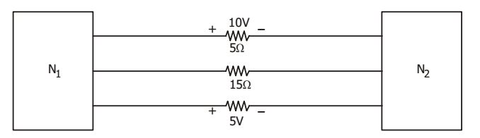
- The two electric sub-networks N1 and N2 are connected through three resistors as shown in the figure below. The voltage across 5 Ω resistor and 1 Ω resistor are given to be 10V and 5V respectively. Then voltage across 15 Ω resistor is
-
View Hint View Answer Discuss in Forum
By KCL, if we take a cutset along all three branches, then total current at the junction is zero.
i.e. I 1 + I 2 + I 3 = 0⇒ 10 + I2 + 5 = 0 5 1
⇒ I2 = 7A
and V = – 105 V.Correct Option: A
By KCL, if we take a cutset along all three branches, then total current at the junction is zero.
i.e. I 1 + I 2 + I 3 = 0⇒ 10 + I2 + 5 = 0 5 1
⇒ I2 = 7A
and V = – 105 V.

