Electric circuits miscellaneous
- A balanced star-connected load with impedance of 20 ∠– 300 ohm is supplied from a 3-phase, 4-wire, 173 volts system, the voltages to neutral being 100 ∠– 900, 100 ∠– 300 and 100 ∠– 1500 V. The current in the neutral wire is _______ A
-
View Hint View Answer Discuss in Forum
Since applied 3-phase voltage is balanced and the impedances are all equal, the currents also would be balanced, as a result there is no current in the neutral wire.
Correct Option: D
Since applied 3-phase voltage is balanced and the impedances are all equal, the currents also would be balanced, as a result there is no current in the neutral wire.
- The voltage transfer ratio V2/ V1 for the network shown in the figure is ________

-
View Hint View Answer Discuss in Forum
Assume a current flowing as shown.
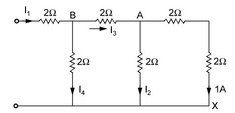
V2 = 1 × 4 = 4V.I1 = 4 = 2A 2
I 2 = 2 + 1 = 3 A.
VA = V2 + 3 × 2
= 4 + 6 = 10 V.I3 = 10 = 5 A 2
I 4 = I3 + I2 = 8A.
V2 = VA + 8 × 2
= 10 + 16 = 26 V.V2 = 4 = 2 V1 26 13
Correct Option: B
Assume a current flowing as shown.
V2 = 1 × 4 = 4V.I1 = 4 = 2A 2
I 2 = 2 + 1 = 3 A.
VA = V2 + 3 × 2
= 4 + 6 = 10 V.I3 = 10 = 5 A 2
I 4 = I3 + I2 = 8A.
V2 = VA + 8 × 2
= 10 + 16 = 26 V.V2 = 4 = 2 V1 26 13
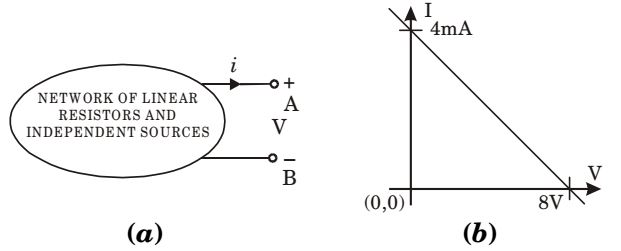
- The v-i characteristics as seen from the terminal pair (A, B) of the network of Fig. (a) is shown in the Fig. (b). If an inductance of value 6 mH is connected across the terminal-pair (A, B), the time constant of the system will be _______μ sec
-
View Hint View Answer Discuss in Forum
The network, as viewed across the terminals can be described by
v = 8 – i × 200
∴ Rint = 2000 ohms.Time constant of the system becomes, T = L = 6 × 10-3 = 3 μs R 2 × 10³
Correct Option: D
The network, as viewed across the terminals can be described by
v = 8 – i × 200
∴ Rint = 2000 ohms.Time constant of the system becomes, T = L = 6 × 10-3 = 3 μs R 2 × 10³
- In the circuit shown in the figure, if the power consumed by the 5 ohm resistor is 10 W, then the power factor of the circuit is _______
-
View Hint View Answer Discuss in Forum
Power consumed by 5 ohm resistor = 10 W
∴ Current, I = √P √R = √10 = √2 A √5
Power consumed by the 10 ohm resistor = 2 × 10 = 20 W
Total power consumed = 30 WCircuit volt ampere = 50 × √2 = 50 W √2 ∴ Power factor = 30 = 0.6 (lagging) 50 Correct Option: B
Power consumed by 5 ohm resistor = 10 W
∴ Current, I = √P √R = √10 = √2 A √5
Power consumed by the 10 ohm resistor = 2 × 10 = 20 W
Total power consumed = 30 WCircuit volt ampere = 50 × √2 = 50 W √2 ∴ Power factor = 30 = 0.6 (lagging) 50
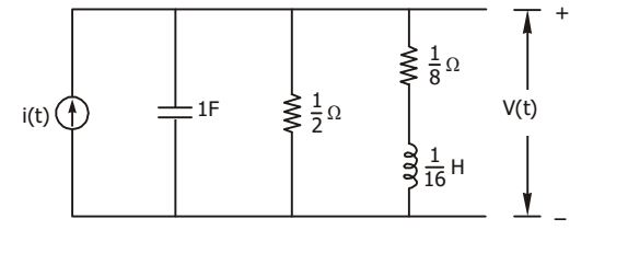
- In the circuit shown in the figure, i(t) is a unit step current. The steady-state value of v(t) is _______ .
-
View Hint View Answer Discuss in Forum
At steady state, since capacitor is open and inductor short circuited, therefore current through 1 Ω 8 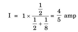
and V(t) = 4 × 1 = 0.1 Volt 5 8
Correct Option: A
At steady state, since capacitor is open and inductor short circuited, therefore current through 1 Ω 8 and V(t) = 4 × 1 = 0.1 Volt 5 8

