Electric circuits miscellaneous
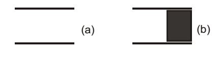
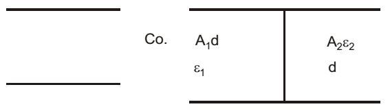
- C0 is the capacitance of parallel plate capacitor with air as dielectric (as in figure (a)). If, half of the entire gap as shown in figure (b) is filled with a dielectric of permittivity ∈r, the expression for the modified capacitance is
-
View Hint View Answer Discuss in Forum
C0 = ∈0 A d
Now C = C1 + C2∴ C = A1 ∈1 + A2 ∈2 d d = A ∈0 + A ∈r ∈0 2d 2d C = A ∈0 (1 + ∈r) 2d C = C0 (1 + ∈r) 2 (∵ C0 = A ∈0 ) d
Correct Option: A
C0 = ∈0 A d
Now C = C1 + C2∴ C = A1 ∈1 + A2 ∈2 d d = A ∈0 + A ∈r ∈0 2d 2d C = A ∈0 (1 + ∈r) 2d C = C0 (1 + ∈r) 2 (∵ C0 = A ∈0 ) d
-
If two-port network shown in the given figure has the constant B = 2s + 1 s2
then z(s) will be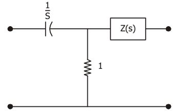
-
View Hint View Answer Discuss in Forum
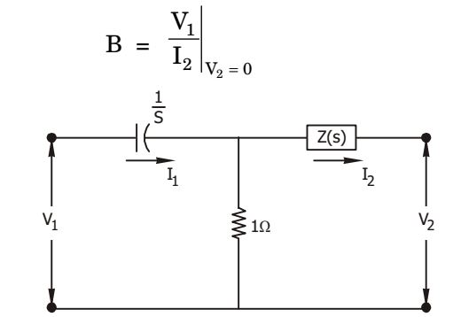
If V2 = 0, thenI1(s) = V1 (s) Z (s) + 1 Z (s) + 1 s and I2 (s) = I1 × 1 = V1(s).s Z(s) + 1 sZ(s) + [1 + Z(s)] Given : B = 2s + 1 s2 ∴ V1(s) = sZ(s) + (1 + V(s)) = 2 + 1 I2(s) s s s2 ⇒ (s + 1)z(s) = (s + 1) s s2 ⇒ Z(s) = 1 s
Correct Option: B
If V2 = 0, thenI1(s) = V1 (s) Z (s) + 1 Z (s) + 1 s and I2 (s) = I1 × 1 = V1(s).s Z(s) + 1 sZ(s) + [1 + Z(s)] Given : B = 2s + 1 s2 ∴ V1(s) = sZ(s) + (1 + V(s)) = 2 + 1 I2(s) s s s2 ⇒ (s + 1)z(s) = (s + 1) s s2 ⇒ Z(s) = 1 s
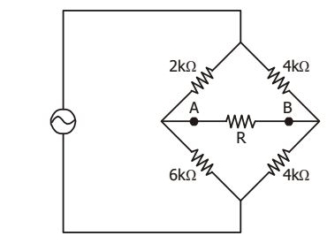
- Value of the resistance R, connected across the terminals A and B, (see given figure), which will absorb maximum power, is __________ kΩ
-
View Hint View Answer Discuss in Forum
The circuit is drawn below by shorting the voltage source.
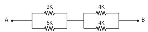
Taking Thevenin's equivalent between points A, B, we haveRTh = 
6 × 3 + 4 × 4 
kΩ = 4 kΩ 6 + 3 4 + 4
For maximum power transfer, R = RTh = 4kΩCorrect Option: A
The circuit is drawn below by shorting the voltage source.
Taking Thevenin's equivalent between points A, B, we haveRTh = 6 × 3 + 4 × 4 kΩ = 4 kΩ 6 + 3 4 + 4
For maximum power transfer, R = RTh = 4kΩ
- For the circuit shown in the given figure, if input impedance Z1 at port 1 is given by
Z1 = K1 (s + 2) s + 5
then input impedance Z2 at port 2 will be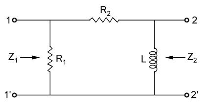
-
View Hint View Answer Discuss in Forum
Z1 = K1 (s + 2) s + 5 ∴ Z1 = R1 (R2 + Ls) R1 + R2 + Ls = R1L 
R2 
L + (s) L R1 + R2 L + (s) = R1 R2 L + (s) R1 + R2 L + (s)
∴ R1 = K1R2 = 2 , R1 + R2 = 5 L L Again , R2 = 2 K1 , L = K 3 3 ∴ Z2 = Ls(R1 + R2) Ls + R2Cs = K1 K1 + 2 3s 3K1 K1 sK1 + 2 3 3K1 = s 5 3K1 = K2s (s + 5) (s + 5) ∴ K2 = 5 K1 3
Correct Option: C
Z1 = K1 (s + 2) s + 5 ∴ Z1 = R1 (R2 + Ls) R1 + R2 + Ls = R1L R2 L + (s) L R1 + R2 L + (s) = R1 R2 L + (s) R1 + R2 L + (s)
∴ R1 = K1R2 = 2 , R1 + R2 = 5 L L Again , R2 = 2 K1 , L = K 3 3 ∴ Z2 = Ls(R1 + R2) Ls + R2Cs = K1 K1 + 2 3s 3K1 K1 sK1 + 2 3 3K1 = s 5 3K1 = K2s (s + 5) (s + 5) ∴ K2 = 5 K1 3
- A combination of 1mF capacitor with an initial voltage vc (0) = – 2V in series with a 100 Ω resistor is connected to a 20 mA ideal dc current source by operating both switches at t = 0s as shown. Which of the following graphs shown in the options approximates the voltage vs across the current source over the next few second?

-
View Hint View Answer Discuss in Forum
Under steady state condition,
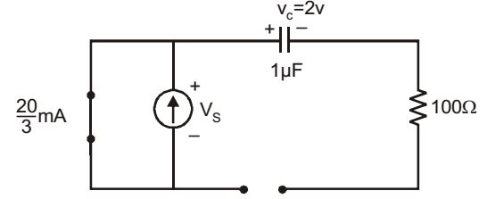
When switch is opened :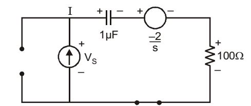
By using Laplace transform approach.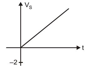
V (S) = 1 1 + 1 100 + -2 S SC S S VS(S) = 20 × 103 S2 ⇒ VS(S) = 2 × 10⁴ S2
VS(t) = 2 × 10⁴
Correct Option: C
Under steady state condition,
When switch is opened :
By using Laplace transform approach.V (S) = 1 1 + 1 100 + -2 S SC S S VS(S) = 20 × 103 S2 ⇒ VS(S) = 2 × 10⁴ S2
VS(t) = 2 × 10⁴

