-
A combination of 1mF capacitor with an initial voltage vc (0) = – 2V in series with a 100 Ω resistor is connected to a 20 mA ideal dc current source by operating both switches at t = 0s as shown. Which of the following graphs shown in the options approximates the voltage vs across the current source over the next few second?

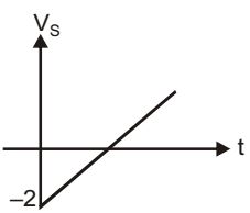
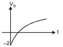

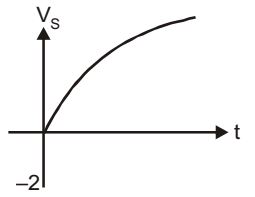
Correct Option: C
Under steady state condition,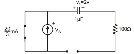
When switch is opened :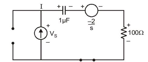
By using Laplace transform approach.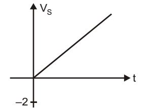
| V (S) = |  |  |  |  | + | | | 100 + | | | |||||
| S | SC | S | S |
| VS(S) = | ||
| S2 |
| ⇒ VS(S) = | ||
| S2 |
VS(t) = 2 × 10⁴

