Electric circuits miscellaneous
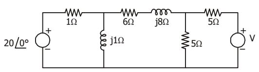
- In the given circuit, if the power dissipated in the 6 Ω resistor is zero then V is
-
View Hint View Answer Discuss in Forum
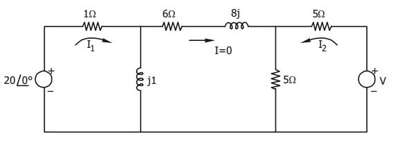
From the circuit, 20 ∠ 0° = I1 (1 + j)⇒ I1 = 20 1 + j and, 20 ∠ 0° = I1 + 5I2 = 20 + 5I2 1 + j ⇒ 5I2 = 20 1 + j Then , V = 10I2 = 2 . 20 = 40j 1 + j 1 + j
= 20 √2 ∠ 45°
Correct Option: A
From the circuit, 20 ∠ 0° = I1 (1 + j)⇒ I1 = 20 1 + j and, 20 ∠ 0° = I1 + 5I2 = 20 + 5I2 1 + j ⇒ 5I2 = 20 1 + j Then , V = 10I2 = 2 . 20 = 40j 1 + j 1 + j
= 20 √2 ∠ 45°
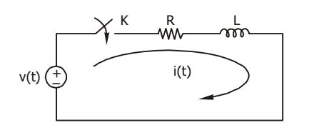
- In the circuit shown in the given figure, switch K is closed at t = 0. The circuit was initially relaxed. Which one of the following sources of v(t) will produce maximum current at t = 0+ ?
-
View Hint View Answer Discuss in Forum
For unit step source,
I(t) = V 
1 - e(-R / L)t 
R
At t = 0, I (t) = 0For ramp, inputI (t) I(t) = V 
tUt - 1 - e(-R / L)t 
R
At t = 0, I(t) = 0For impulse input, I(t) = V e(-R / L)t R Then at t = 0, I(t) = V Maximum R
Correct Option: B
For unit step source,
I(t) = V 1 - e(-R / L)t R
At t = 0, I (t) = 0For ramp, inputI (t) I(t) = V tUt - 1 - e(-R / L)t R
At t = 0, I(t) = 0For impulse input, I(t) = V e(-R / L)t R Then at t = 0, I(t) = V Maximum R
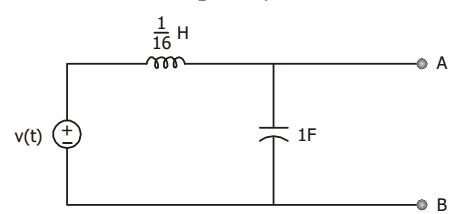
- The circuit shown in the given figure, will act as an ideal current source with respect to terminal A and B, when frequency is
-
View Hint View Answer Discuss in Forum
Redrawing equivalent circuit

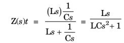
⇒ Z(jω) = jωL 1 - LCω2
For ideal current source, Z(jω) = ∞
⇒ 1 – LCω2 = 0⇒ ω = 1 = 4 rad /sec √LC Correct Option: C
Redrawing equivalent circuit
⇒ Z(jω) = jωL 1 - LCω2
For ideal current source, Z(jω) = ∞
⇒ 1 – LCω2 = 0⇒ ω = 1 = 4 rad /sec √LC
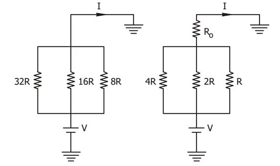
- The circuit shown in Fig-I is replaced by that in FigII. If current I remains the same, then R0 will be
-
View Hint View Answer Discuss in Forum
From Fig. (a),
I = V + V + V = 7V 32R 16R 8R 32R
From Fig. (b),I = (V - IR0) 1 + 1 + 1 = 7(V- IR0) 4R 2R R 4R
Since current remains same∴ 7(V- IR0) = 7V 4R 32R ⇒ (V- IR0) = V 8 ⇒ IR0 = 7V = 4R.I 8
⇒ R0 = 4RCorrect Option: D
From Fig. (a),
I = V + V + V = 7V 32R 16R 8R 32R
From Fig. (b),I = (V - IR0) 1 + 1 + 1 = 7(V- IR0) 4R 2R R 4R
Since current remains same∴ 7(V- IR0) = 7V 4R 32R ⇒ (V- IR0) = V 8 ⇒ IR0 = 7V = 4R.I 8
⇒ R0 = 4R
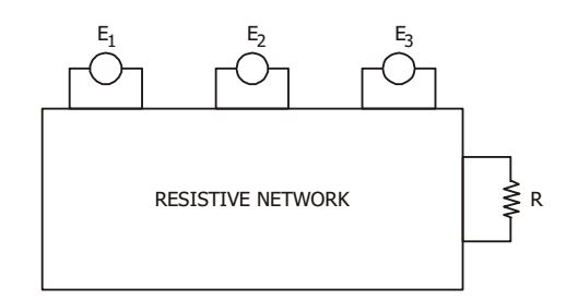
- In the circuit given in the figure, the power consumed in the resistance R is measured when one source is acting at a time, these values are 18 W, 50 W and 98 W. When all the sources are acting simultaneously, possible maximum and minimum values of power in R will be
-
View Hint View Answer Discuss in Forum
P1 = 18 = E12 R P2 = 50 = E22 R P3 = 98 = E32 R Maximum power, Pmax = (E1 + E2 + E3)2 R = E12 + E22 + E32 + 2E1E2 + 2E2E3 + 2E3E1 R
⇒ Pmax = P1 + P2 + P3 + 2(√P1P2 + √P2P3 + √P3P1)
= 18 + 50 + 98 + 2 √18 × 50 + 2 √50 × 98 + 2 √18 × 98 = 450 wattsMinimum power, Pmax = (E1 - E2 - E3)2 R
= P1 + P2 + P3 - 2√P1P3 - 2√P2P3 + 2√P1P2)
= 18 + 50 + 98 - 2 √18 × 98 - 2 √50 × 98 + 2 √18 × 50 = 2 watts
Correct Option: C
P1 = 18 = E12 R P2 = 50 = E22 R P3 = 98 = E32 R Maximum power, Pmax = (E1 + E2 + E3)2 R = E12 + E22 + E32 + 2E1E2 + 2E2E3 + 2E3E1 R
⇒ Pmax = P1 + P2 + P3 + 2(√P1P2 + √P2P3 + √P3P1)
= 18 + 50 + 98 + 2 √18 × 50 + 2 √50 × 98 + 2 √18 × 98 = 450 wattsMinimum power, Pmax = (E1 - E2 - E3)2 R
= P1 + P2 + P3 - 2√P1P3 - 2√P2P3 + 2√P1P2)
= 18 + 50 + 98 - 2 √18 × 98 - 2 √50 × 98 + 2 √18 × 50 = 2 watts

