Electric circuits miscellaneous
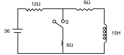
- In the circuit shown in the figure, the switch S has been opened for long time. It is closed at t = 0. For t > 0, the current flowing through the inductor will be given by
-
View Hint View Answer Discuss in Forum
At the instant of closing the switch, current through the inductor
= 36 = 2 A 12 + 6
Under steady state conditions after closing of the switch,current = 36 + 6 = 6 A 15 12 5
Here the equation which satisfies is
iL (t) = 1.2 + 0.8 e– 2tCorrect Option: A
At the instant of closing the switch, current through the inductor
= 36 = 2 A 12 + 6
Under steady state conditions after closing of the switch,current = 36 + 6 = 6 A 15 12 5
Here the equation which satisfies is
iL (t) = 1.2 + 0.8 e– 2t
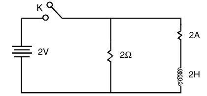
- In the network shown in the figure, the circuit was initially in the steady-state condition with the switch K closed. At the instant when the switch is opened, the rate of decay of current through the inductance will be
-
View Hint View Answer Discuss in Forum
Current in the inductor of the instant of opening the switch in 1 A. Thereafter
i(t) = 1e(– L / R)C = e– 2t⇒ di(t) = 2 e– 2t dt 
Correct Option: D
Current in the inductor of the instant of opening the switch in 1 A. Thereafter
i(t) = 1e(– L / R)C = e– 2t⇒ di(t) = 2 e– 2t dt
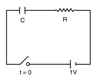
- In the series Rc circuit shown in the figure, the voltage across C starts increasing when the d.c. source is switched on. The rate of increase of voltage across C at the instant just after the switch is closed (i.e. at t = 0+) will be
-
View Hint View Answer Discuss in Forum
Voltage across the capacitor at any time t, Vc = V (l – e– t / RC)
= l – e– t / RC ... (since V = 1 volt)∴ dVc = 1 e– t / RC dt RC At t = 0+ , dVc = 1 dt RC
Correct Option: D
Voltage across the capacitor at any time t, Vc = V (l – e– t / RC)
= l – e– t / RC ... (since V = 1 volt)∴ dVc = 1 e– t / RC dt RC At t = 0+ , dVc = 1 dt RC
- A periodic rectangular signal X(t) has the wave form shown in the figure. Frequency of the fifth harmonic of its spectrum is

-
View Hint View Answer Discuss in Forum
Periodic time = 4 ms = 4 × 10 – 3 sec.
Fundamental frequency = 103 = 250 Hz 4
∴ Frequency of the 5th harmonic = 250 × 5 = 1250 Hz
Correct Option: D
Periodic time = 4 ms = 4 × 10 – 3 sec.
Fundamental frequency = 103 = 250 Hz 4
∴ Frequency of the 5th harmonic = 250 × 5 = 1250 Hz
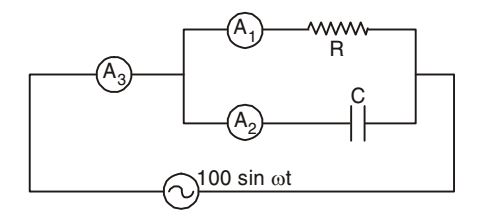
- In the given figure, A1, A2 and A3 are ideal ammeters. If A1 reads 5A, A2 reads 12 A, then A3 should read
-
View Hint View Answer Discuss in Forum
Since the source is an a.c voltage, therefore
I 3rms = √I1rms ² + I2rms ²
= √5² +12² = 13 ACorrect Option: C
Since the source is an a.c voltage, therefore
I 3rms = √I1rms ² + I2rms ²
= √5² +12² = 13 A

