-
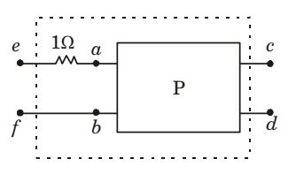
The two-port network P shown in the figure has ports 1 and 2, denoted by terminals (a, b) and (c, d) respectively. It has an impedance matrix Z with parameters denoted by zij . A 1 Ω resistor is connected in series with the network at port 1 as shown in the figure. The impedance matrix of the modified two-port networ k (shown as a dashed box) is
-
-

z11 + 1 z12 + 1 
z21 z22 + 1 -
z11 + 1 z12 z21 z22 + 1 -
z11 + 1 z12 z21 z22 -
z11 + 1 z12 z21 + 1 z22
-
Correct Option: C
Case 1 
V1 = Z11 i 1 + Z12 i 2
V2 = Z21 i 1 + Z22 i2
Case 2 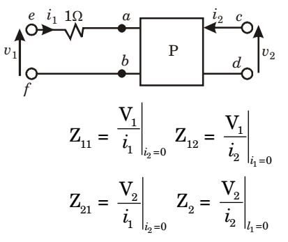
Equivalent circuits
For case 1 : Z11 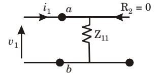
For case 2 : 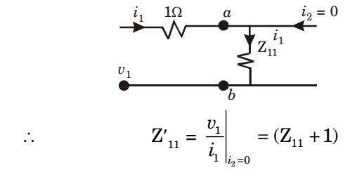
For case 1 : 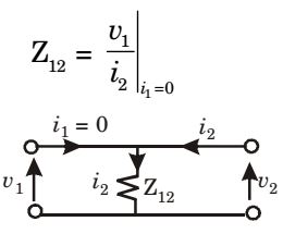
For case 2 : 
Z21 for case 1 :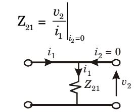
For case 2 :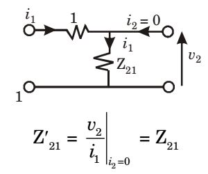
Z22 for case 1 :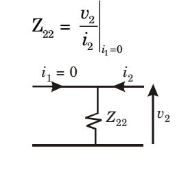
For case 2 :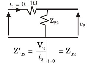
∴ New impedance matrix,
| Z' = |  | Z11 + 1 |  | ||||
| Z21 | Z22 |

