Network Elements and the Concept of Circuit
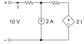
- The current I in the circuit will given by—
-
View Hint View Answer Discuss in Forum
Applying the KVL
10 = 1 I + 2 (I + 2) + 2 I
10 = I + 2 I + 4 + 2 I
10 – 4 = 5II = 6 = 1.2 amp. 5
Correct Option: B
Applying the KVL
10 = 1 I + 2 (I + 2) + 2 I
10 = I + 2 I + 4 + 2 I
10 – 4 = 5II = 6 = 1.2 amp. 5
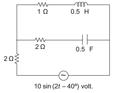
- The complex power in the circuit shown below will be—
-
View Hint View Answer Discuss in Forum
Complex power is given by the relation
P = I V
given V = 10 sin (2t – 40°)V
for the given circuit
10 sin (2t – 40°) voltZ eq = 2 + 
2 + 1 
|| (1 + 5s) 5s
= 3.02 ∠ 6.3° at ω = 2I = V = 10 sin (2t – 40°) Zeq 3.02 – 6.3°
I = 3.3 sin (2t – 46.3°)
so, complex powerP = VI = Vm Im cos φ 2 P = 10 × 3.3 ∠ – 6.3° 2
or P = 16.5 ∠ – 6.3° wattsCorrect Option: A
Complex power is given by the relation
P = I V
given V = 10 sin (2t – 40°)V
for the given circuit
10 sin (2t – 40°) voltZ eq = 2 + 2 + 1 || (1 + 5s) 5s
= 3.02 ∠ 6.3° at ω = 2I = V = 10 sin (2t – 40°) Zeq 3.02 – 6.3°
I = 3.3 sin (2t – 46.3°)
so, complex powerP = VI = Vm Im cos φ 2 P = 10 × 3.3 ∠ – 6.3° 2
or P = 16.5 ∠ – 6.3° watts
- For a given voltage four heating coils will produce max. heat when connected in—
-
View Hint View Answer Discuss in Forum
[(A), (C)] (i) When all in parallel
heat produced, P = V2 Req 
R e q = R 4 or P = 4V2 ....(i) R
(ii) When all in series
P = V2 = 2√2 V2 .....(ii) Req 4R
(iii) With two parallel pairs in series
P = P1 + P 2= V2 + V2 Req Req = V2 + V2 = 2V2 + V2 = 5V2 R/2 2R R 2R 2R
(iv) One pair in parallel with other two in series
P = P1 + P 2
= V2 R/2 + V2 2R = 2V2 R + V2 2R = 5V2 2R
From above discussion we see that heat in case (i) and (iii) is maximum so the alternative (A) and (C) are correct.Correct Option: E
When all in parallel
heat produced, P = V2 Req R e q = R 4 or P = 4V2 ....(i) R
(ii) When all in seriesP = V2 = 2√2 V2 .....(ii) Req 4R
(iii) With two parallel pairs in series
P = P1 + P 2= V2 + V2 Req Req = V2 + V2 = 2V2 + V2 = 5V2 R/2 2R R 2R 2R
(iv) One pair in parallel with other two in series
P = P1 + P 2
= V2 R/2 + V2 2R = 2V2 R + V2 2R = 5V2 2R
From above discussion we see that heat in case (i) and (iii) is maximum so the alternative (A) and (C) are correct.
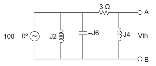
- The Thevenin equivalent voltage Vm appearing between the terminals A and B of the network shown is given by—
-
View Hint View Answer Discuss in Forum
If we see the given network carefully, we get that there are two extra reduntant elements present in the circuit are J2, – J6. Because voltage at these element is independent.
Now apply potential divider rule between 3, J4 element.Vm = J4 × 100 ∠ 0° = J4 × 100 ∠ 0° (3 – J4) 3 + J4 3 + J4 3 - J4
= 16 (4 + 3J)Correct Option: B
If we see the given network carefully, we get that there are two extra reduntant elements present in the circuit are J2, – J6. Because voltage at these element is independent.
Now apply potential divider rule between 3, J4 element.Vm = J4 × 100 ∠ 0° = J4 × 100 ∠ 0° (3 – J4) 3 + J4 3 + J4 3 - J4
= 16 (4 + 3J)
- Given T.F. H (s) = s + 2 / s2 + s + 4, under steady state condition, the sinusoidal input and output are respectively—
x (t) = cos 2t
y (t) = cos (2t + φ), then angle φ of will be
-
View Hint View Answer Discuss in Forum
Given T.F.
H(s) = Y (s) = s + 2 ....(i) X (s) s2 + s + 4
x (t) = cos 2t
y (t) = cos (2t + φ)
from x (t) = cos 2t we concluded that ω = 2
on putting s = J ω = J 2. in equation (i) we getH (2 J) = 2J + 2 = 2(1 + 1) –J2 22 + 2J + 4 – 4 + 2J + 4 = 2(1 + J) = 2√2 ∠ 45° 2.J ∠ 90° or y (t) = ∠ (45º– 90º) = ∠ – 45º y (t)
Correct Option: C
Given T.F.
H(s) = Y (s) = s + 2 ....(i) X (s) s2 + s + 4
x (t) = cos 2t
y (t) = cos (2t + φ)
from x (t) = cos 2t we concluded that ω = 2
on putting s = J ω = J 2. in equation (i) we getH (2 J) = 2J + 2 = 2(1 + 1) –J2 22 + 2J + 4 – 4 + 2J + 4 = 2(1 + J) = 2√2 ∠ 45° 2.J ∠ 90° or y (t) = ∠ (45º– 90º) = ∠ – 45º y (t)

