Network Elements and the Concept of Circuit
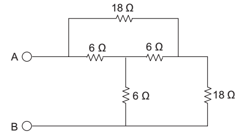
- The Resistance RAB in the circuit is—
-
View Hint View Answer Discuss in Forum
First change the given star into delta

RAB = 18 || (9 + 9) = 9 Ω

Correct Option: D
First change the given star into delta
RAB = 18 || (9 + 9) = 9 Ω
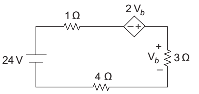
- The power delivered by the dependent source—
-
View Hint View Answer Discuss in Forum
Let the current I is flowing through the circuit. Apply KVL to the loop

24 – i.1 + 2Vb + 3i – 4i = 0
24 = 8i – 2Vb (∵ Vb = 3i)
24 = 81 – 2 × 3i = 8i – 6i
24 = 2i
i = 12 amp.
In order to calculate the power delivered by the dependent source put all the power dissipated across the resistance equal to power declined by the different dependent and independent sources. Power delivered by the sources = power dissipated across the resistor Power delivered by the dependent source
+ 24 × i = i 2 × 3 + i 2 × 4 + i 2 × 1
or Power delivered by the dependent source = i 2 8 – 24 i = (12)2 × 8 – 24 × 12
= 144 × 8 – 288 = 864 wattsCorrect Option: A
Let the current I is flowing through the circuit. Apply KVL to the loop
24 – i.1 + 2Vb + 3i – 4i = 0
24 = 8i – 2Vb (∵ Vb = 3i)
24 = 81 – 2 × 3i = 8i – 6i
24 = 2i
i = 12 amp.
In order to calculate the power delivered by the dependent source put all the power dissipated across the resistance equal to power declined by the different dependent and independent sources. Power delivered by the sources = power dissipated across the resistor Power delivered by the dependent source
+ 24 × i = i 2 × 3 + i 2 × 4 + i 2 × 1
or Power delivered by the dependent source = i 2 8 – 24 i = (12)2 × 8 – 24 × 12
= 144 × 8 – 288 = 864 watts
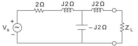
- Which one of the following impedance values of load will cause maximum power to be transferred to the load for the network shown in the given figure?
-
View Hint View Answer Discuss in Forum
In order to transfer the maximum power to the load
ZL = Z*m (i.e. complex conjugate of the thevenin impedance)
Calculation for Zth:
Zth = J2 + (2 + J2) || – J2= J2 + (2 + J2) (–J2) 2 + J2 – J2 = J2 + J4 – J24 2 
= 4J – J4 – J24 2 = 4 = 2 Ω 2 Correct Option: D
In order to transfer the maximum power to the load
ZL = Z*m (i.e. complex conjugate of the thevenin impedance)
Calculation for Zth:
Zth = J2 + (2 + J2) || – J2= J2 + (2 + J2) (–J2) 2 + J2 – J2 = J2 + J4 – J24 2 = 4J – J4 – J24 2 = 4 = 2 Ω 2
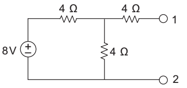
- For the figure shown below the Norton's equivalent parameter will be—
-
View Hint View Answer Discuss in Forum
Calculation for Isc

I = 8 = 8 Req 4 + (4 || 4) 
or I = 8 = 4 4 + 2 3 Is c = I × 4 = - 4 2 amp. 4 + 4 3 x 2 3
Calculation for Rth or R
RN = 4 || 4 + 4
= 2 + 4
= 6 ΩCorrect Option: A
Calculation for Isc
I = 8 = 8 Req 4 + (4 || 4) or I = 8 = 4 4 + 2 3 Is c = I × 4 = - 4 2 amp. 4 + 4 3 x 2 3
Calculation for Rth or R
RN = 4 || 4 + 4
= 2 + 4
= 6 Ω
- Which one of the following combinations of open circuit voltage and Thevenin's equivalent resistance represents the Thevenin's equivalent of the circuit shown below in the figure?
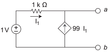
-
View Hint View Answer Discuss in Forum
Calculation for Rth:
Let an imaginary voltage source (say 5V) is applied through the terminal a and b, and assume that current I is flowing due to this source so Rth will be the ratio of V/I.
Apply KVL 5 = 1000 I1I 1 = 
- 5 
1000
I = 99 I1 + I1 = 100 I1Rth = IC = - 5 5 = 10 Ω (sign neglected) I 100 I1 100(5 / 10000)
Calculation for Vth
Apply KCL at node A
I1 + 99 I1 = 0
I 1 = 0
Now, the circuit becomes
I 1 = 0, shows that there will be no drop across 1 kΩ resistance.
Hence Vth = 1 VCorrect Option: A
Calculation for Rth:
Let an imaginary voltage source (say 5V) is applied through the terminal a and b, and assume that current I is flowing due to this source so Rth will be the ratio of V/I.
Apply KVL 5 = 1000 I1I 1 = - 5 1000
I = 99 I1 + I1 = 100 I1Rth = IC = - 5 5 = 10 Ω (sign neglected) I 100 I1 100(5 / 10000)
Calculation for Vth
Apply KCL at node A
I1 + 99 I1 = 0
I 1 = 0
Now, the circuit becomes
I 1 = 0, shows that there will be no drop across 1 kΩ resistance.
Hence Vth = 1 V

