Network Elements and the Concept of Circuit
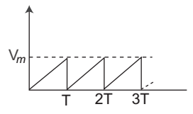
- Find the rms value of the wave shown below—.
-
View Hint View Answer Discuss in Forum
Remember always rms value of given periodic wave is
Vm . √3
Correct Option: A
Remember always rms value of given periodic wave is
Vm . √3
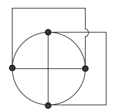
- The number of branches and nodes in the graph are—
-
View Hint View Answer Discuss in Forum
NA
Correct Option: B
NA
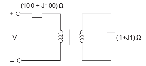
- In the figure the transformer is ideal with adjustable turns ratio N2 / N1 . The turns ratio N2 / N1 for maximum power transfer to the load is—
-
View Hint View Answer Discuss in Forum
As given that transformer is ideal it means
I1 = I2 = I (say)
so, V1 = I1 (100 + J100) = I (100+ J100) = 100 I1 (J+ 1)
and V2 = I2 (1 + J) = I (1 + J)So, V2 = N2 = (1 + J) I = 1 V1 N1 100! (1 + J) 100 N2 = 1: 100 N1 Correct Option: C
As given that transformer is ideal it means
I1 = I2 = I (say)
so, V1 = I1 (100 + J100) = I (100+ J100) = 100 I1 (J+ 1)
and V2 = I2 (1 + J) = I (1 + J)So, V2 = N2 = (1 + J) I = 1 V1 N1 100! (1 + J) 100 N2 = 1: 100 N1
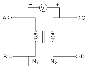
- A single phase transformer is connected as shown in fig. when a voltage of 100 V (rms) was applied across AB, the voltmeter connected across AC measured 100 V (rms). The turns ratio N1: N2 is—
-
View Hint View Answer Discuss in Forum
Since the reading of voltameter is 100 Vrms it means the output voltage is equal to
V2 = 100 + 100 = 200 VrmsSo, V2 = N2 = 200 = 2 V1 N1 100 1
or N1: N2 = 1: 2Correct Option: B
Since the reading of voltameter is 100 Vrms it means the output voltage is equal to
V2 = 100 + 100 = 200 VrmsSo, V2 = N2 = 200 = 2 V1 N1 100 1
or N1: N2 = 1: 2
- A capacitor is charged by a square wave current source, the voltage across the capacitor is—
-
View Hint View Answer Discuss in Forum
Voltage across the capacitor is given by the relation
V = 1 ∫ i dt Where, i = square wave C
since the integration of square wave gives triangular wave so the voltage across the capacitor will be like a triangular wave.Correct Option: B
Voltage across the capacitor is given by the relation
V = 1 ∫ i dt Where, i = square wave C
since the integration of square wave gives triangular wave so the voltage across the capacitor will be like a triangular wave.

