Network Elements and the Concept of Circuit
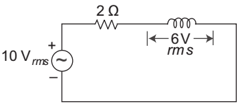
- The rms value of the current in the a.c. circuit as shown below in the figure will be—
-
View Hint View Answer Discuss in Forum
Since, 102 = V2 Rrms + V2Lrms
100 = V2 Rrms + 36
V2 Rrms = 100 – 36 = 64
V2 Rrms = 64 = 8i = V2 Rrms = 8 = 4 A R 2 Correct Option: B
Since, 102 = V2 Rrms + V2Lrms
100 = V2 Rrms + 36
V2 Rrms = 100 – 36 = 64
V2 Rrms = 64 = 8i = V2 Rrms = 8 = 4 A R 2
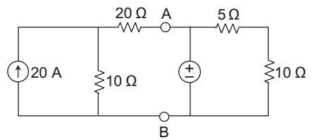
- The value of Thevenin resistance for the given figure shown below between A and B will be—
-
View Hint View Answer Discuss in Forum
The Thevenin resistance can be calculate by drawing its equivalent circuit.

RAB = Rth = 30 || 0 || 15
= 0 ΩCorrect Option: D
The Thevenin resistance can be calculate by drawing its equivalent circuit.
RAB = Rth = 30 || 0 || 15
= 0 Ω
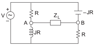
- What will be the value of Rth between A and B for the given circuit shown below?
-
View Hint View Answer Discuss in Forum
Rth can be calculated by opening the load terminal and all the energy sources replaced by their internal resistance the circuit becomes

Rth = R || JR + R || – JR= R. JR + R (–JR) = JR - JR R + JR R - JR (1 + J) (1 - J) = JR [1 – J – (1 + J)] = JR [– J – 1 – J] 1 + J2 1 – (–1) = JR (–2J) = – 2R J2 = R 2 2 Correct Option: D
Rth can be calculated by opening the load terminal and all the energy sources replaced by their internal resistance the circuit becomes
Rth = R || JR + R || – JR= R. JR + R (–JR) = JR - JR R + JR R - JR (1 + J) (1 - J) = JR [1 – J – (1 + J)] = JR [– J – 1 – J] 1 + J2 1 – (–1) = JR (–2J) = – 2R J2 = R 2 2
- A Network is said to be linear if and only if—
-
View Hint View Answer Discuss in Forum
NA
Correct Option: D
NA
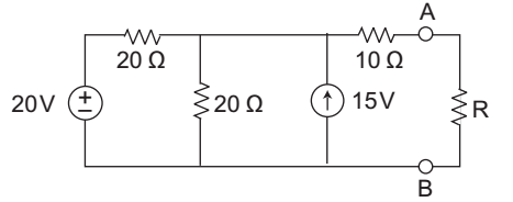
- The value of R required for maximum power transfer in the network shown below is—
-
View Hint View Answer Discuss in Forum
We know for maximum power transfer to the network Rth = RL
Calculation for Rth:
Rth = 20 || 20 + 10 = 10 + 10 = 20 ΩCorrect Option: B
We know for maximum power transfer to the network Rth = RL
Calculation for Rth:
Rth = 20 || 20 + 10 = 10 + 10 = 20 Ω

