Network Elements and the Concept of Circuit
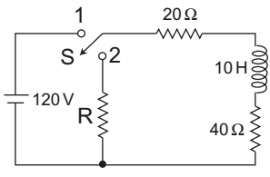
Direction: A coil of inductance 10 H and resistance 40 Ω is connected as shown in the figure. After the switch S has been in contact with point 1 for a very long time, it is moved to poin 2 at t = 0.
- If, at t = 0+, the voltage across the coil is 120V, the value of resistance R is—
-
View Hint View Answer Discuss in Forum
t < 0 connect to 1
i L(0–) = 120 = 2 Amp 20 + 40
i L(0–) = i L(0+) = 2 Amp
t = 0+ connect 2
(60 + R) 2 – 120 = 0
60 + R = 60
or R = 0Ω
Hence alternative (A) is the correct choice.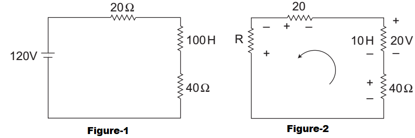
Correct Option: A
t < 0 connect to 1
i L(0–) = 120 = 2 Amp 20 + 40
i L(0–) = i L(0+) = 2 Amp
t = 0+ connect 2
(60 + R) 2 – 120 = 0
60 + R = 60
or R = 0Ω
Hence alternative (A) is the correct choice.
- A series R-L-C circuit is switched on to a step voltage V at t = 0. What are the initial and final values of the current in the circuit, respectively?
-
View Hint View Answer Discuss in Forum
Zero, zero
because at initial capacitor short 4 inductor open and at final capacitor open 4 inductor short.Correct Option: C
Zero, zero
because at initial capacitor short 4 inductor open and at final capacitor open 4 inductor short.
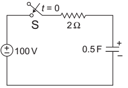
- In figure, the capacitor initially has a charge of 10 coulomb. The current in the circuit one second after the switch S is closed will be—
-
View Hint View Answer Discuss in Forum
I(+) = V e–t/RC R = 100 e–1 / 2 × .5 R
= 18·5 A
Correct Option: B
I(+) = V e–t/RC R = 100 e–1 / 2 × .5 R
= 18·5 A
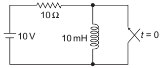
- The circuit shown in the figure is in steady state, when the switch is closed at t = 0. Assuming that the inductance is ideal, the current through the inductor at t = 0+ equals—
-
View Hint View Answer Discuss in Forum
At steady state iL(0–) = 10 = 1Amp 10
i L(0–) = i L(0+) = 1 Amp
Correct Option: C
At steady state iL(0–) = 10 = 1Amp 10
i L(0–) = i L(0+) = 1 Amp
- In the figure given, for the initial capacitor voltage is zero. The switch is closed at t = 0. The final steady-state voltage across the capacitor is—
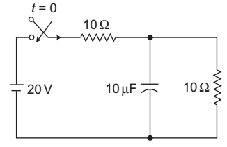
-
View Hint View Answer Discuss in Forum
Capacitor will fully charge act an open.
I = 20 = 1Amp 10 + 10
VC(0–) = 0 (given)
VC(∞) = Voltage across 10Ω terminal VC(∞) = 10 × 1
= 10V
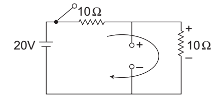
Correct Option: A
Capacitor will fully charge act an open.
I = 20 = 1Amp 10 + 10
VC(0–) = 0 (given)
VC(∞) = Voltage across 10Ω terminal VC(∞) = 10 × 1
= 10V


