Network Elements and the Concept of Circuit
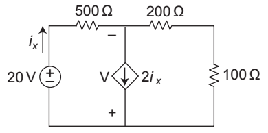
- In the circuit of fig. below power is absorbed by—
-
View Hint View Answer Discuss in Forum
20 – 500 ix – (– ix) (200 + 100) = 0

or 20 = 500 ix – 300 ix
or 20 = 200 ix
or ix = .1 A
(+ve sign of ix means power is delivered by independent source and absorbed by the dependent source.)
Voltage across dependent source,
V = (200 + 100) ix = 300 ix = 300 × .1 = 30 V
Power absorbed by dependent source = V (2ix) = 30 × 2 × .1 = 6 W
Alternative (A) is the correct choice.Correct Option: A
20 – 500 ix – (– ix) (200 + 100) = 0
or 20 = 500 ix – 300 ix
or 20 = 200 ix
or ix = .1 A
(+ve sign of ix means power is delivered by independent source and absorbed by the dependent source.)
Voltage across dependent source,
V = (200 + 100) ix = 300 ix = 300 × .1 = 30 V
Power absorbed by dependent source = V (2ix) = 30 × 2 × .1 = 6 W
Alternative (A) is the correct choice.
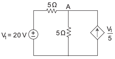
- The dependent source in fig. shown below—
-
View Hint View Answer Discuss in Forum
Let Vx be the voltage a cross dependent source KCL at node A, we get

Vx – 20 + Vx = V1 5 5 5 or Vx – 20 + Vx = 20 (∵ V1 = 20 V) 5 5 5 or Vx = 20 = 4 = + ve 5
It means power is delivered by the dependent source, and is given asP = Vx . Vx = 20 × 20 = 80 W. 5 5 Correct Option: A
Let Vx be the voltage a cross dependent source KCL at node A, we get
Vx – 20 + Vx = V1 5 5 5 or Vx – 20 + Vx = 20 (∵ V1 = 20 V) 5 5 5 or Vx = 20 = 4 = + ve 5
It means power is delivered by the dependent source, and is given asP = Vx . Vx = 20 × 20 = 80 W. 5 5
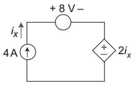
- In the circuit of fig. shown below dependent source—
-
View Hint View Answer Discuss in Forum
Since current ix is enters at the positive terminal of the dependent source. It means power is absorbed by the dependent source, i.e.
P = V. i = 2ix. ix = 2 i2x = 2.42 = 32 W (∵ ix = 4 A)Correct Option: D
Since current ix is enters at the positive terminal of the dependent source. It means power is absorbed by the dependent source, i.e.
P = V. i = 2ix. ix = 2 i2x = 2.42 = 32 W (∵ ix = 4 A)
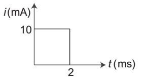
- The current in a 100 µF capacitor is shown below. If capacitor is initially uncharged, then the waveform for the voltage across it is—
-
View Hint View Answer Discuss in Forum
Voltage across capacitor,
V = 1 
t i dt C 0 = 1 2 × 10⁻³ 10 × 10–3 dt 100 × 10–6 0 = 10 × 10–3 × 2 × 10–3 = .2 V 100 × 10–6
This 0.2 V is increases linearly from 0 to 0.2 V up to 2 ms. after that capacitor holds constant voltage i.e. 0.2 V.
Hence alternative (D) is the correct choice.
Correct Option: D
Voltage across capacitor,
V = 1 t i dt C 0 = 1 2 × 10⁻³ 10 × 10–3 dt 100 × 10–6 0 = 10 × 10–3 × 2 × 10–3 = .2 V 100 × 10–6
This 0.2 V is increases linearly from 0 to 0.2 V up to 2 ms. after that capacitor holds constant voltage i.e. 0.2 V.
Hence alternative (D) is the correct choice.
- The incidence matrix of a graph is as given below—

The number of possible tree are—
-
View Hint View Answer Discuss in Forum
No. of possible tree determinant of [A. AT] where A is the reduced incidence matrix and AT is the transpose of reduced incidence matrix. Now

or A. AT = 3 –1 –1 0 –1 3 –1 0 –1 –1 4 –1 0 0 –1 –2
or number of possible trees det [A AT] = det3 –1 –1 0 = 40 –1 3 –1 0 –1 –1 4 –1 0 0 –1 –2 Correct Option: A
No. of possible tree determinant of [A. AT] where A is the reduced incidence matrix and AT is the transpose of reduced incidence matrix. Now
or A. AT = 3 –1 –1 0 –1 3 –1 0 –1 –1 4 –1 0 0 –1 –2
or number of possible trees det [A AT] = det3 –1 –1 0 = 40 –1 3 –1 0 –1 –1 4 –1 0 0 –1 –2

