Network Elements and the Concept of Circuit
- Which of the following theorems can be applied to any network-linear or non-linear, active or passive, time variant or time-invariant?
-
View Hint View Answer Discuss in Forum
Tellegen theorem can be applied to any network i.e.
• Linear or non-linear
• Active or passive
• Time variant or time-invariantCorrect Option: C
Tellegen theorem can be applied to any network i.e.
• Linear or non-linear
• Active or passive
• Time variant or time-invariant
- The circuit shown below is under steady-state condition with the switch closed. The switch is opened at t = 0. What is the time constant of the circuit?

-
View Hint View Answer Discuss in Forum

Time constantτ = L = 2H R 10Ω
or τ = 0.2s.Correct Option: B
Time constantτ = L = 2H R 10Ω
or τ = 0.2s.
- In the circuit shown below, the switch is moved from position A to B at time t = 0. The current i through the inductor satisfies the following conditions—

1. i(0) = – 8A2. di (t = 0) = 3A/s dt
3. i(∞) = 4A The value of R is—
-
View Hint View Answer Discuss in Forum

When the switch in the position B, as shown below.
Writing voltage equation.Ri + L di = E2 ....(A) dt
Taking Laplace transformRI(s) + 2[sI(s) – I(0)] = E2 s or (R + 2) I(s) = E2 – 16 (since, I(0) = – 8A) s or I(s) = E2 – 16 s(R + 2s) (R + 2s) or I(s) = E2 
1 – 2 
– 16 R s R + 2s (R + 2s)
(By using partial fraction)
Taking inverse Laplace transform
i(t) = E2 R 1 – e[–(R/2) t] – 8e–(R/2) t....(B)Given: i(t) = E2 = 4 ....(i) R Again di(0) = 3 = E2 . R + 4R ....(ii) dt R 2
Solving equations (i) and (ii), we get
R = 0.5 ohmCorrect Option: A
When the switch in the position B, as shown below.
Writing voltage equation.Ri + L di = E2 ....(A) dt
Taking Laplace transformRI(s) + 2[sI(s) – I(0)] = E2 s or (R + 2) I(s) = E2 – 16 (since, I(0) = – 8A) s or I(s) = E2 – 16 s(R + 2s) (R + 2s) or I(s) = E2 1 – 2 – 16 R s R + 2s (R + 2s)
(By using partial fraction)
Taking inverse Laplace transform
i(t) = E2 R 1 – e[–(R/2) t] – 8e–(R/2) t....(B)Given: i(t) = E2 = 4 ....(i) R Again di(0) = 3 = E2 . R + 4R ....(ii) dt R 2
Solving equations (i) and (ii), we get
R = 0.5 ohm
Direction: Figure given below shows four light bulbs connected across an 85V battery. The bulbs are said to be connected in parallel.
- Which one of the following is the
ratio V24 V13
of the network shown in the given figure—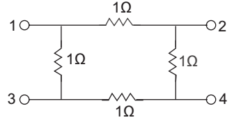
-
View Hint View Answer Discuss in Forum
V13 = 1 (I1 – I) ...........(i)
V24 = 1 × 1 .........(ii)
(I1 – I) 1 = I × 1 + I × 1 + I × 1
or I1 = 4I .......(iii)
and V13 = 4I – I = 3IV24 = 1 = 1 V13 3I 3 Correct Option: A
V13 = 1 (I1 – I) ...........(i)
V24 = 1 × 1 .........(ii)
(I1 – I) 1 = I × 1 + I × 1 + I × 1
or I1 = 4I .......(iii)
and V13 = 4I – I = 3IV24 = 1 = 1 V13 3I 3
- Kirchoff’s laws fail in case of—
-
View Hint View Answer Discuss in Forum
Kirchhoff’s laws fail in case of non-linear networks.
Correct Option: A
Kirchhoff’s laws fail in case of non-linear networks.

