Network Elements and the Concept of Circuit
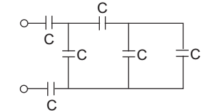
- The equivalent capacitance for the network shown in the fig. is—
-
View Hint View Answer Discuss in Forum
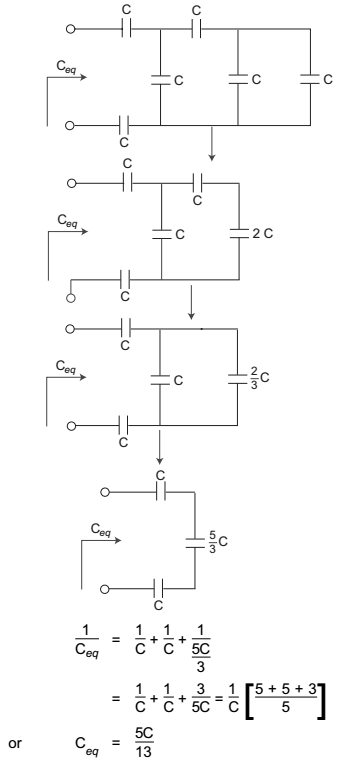
Circuit for equivalent capacitance by applying the concept of series parallel combination of the capacitance
Correct Option: B
Circuit for equivalent capacitance by applying the concept of series parallel combination of the capacitance

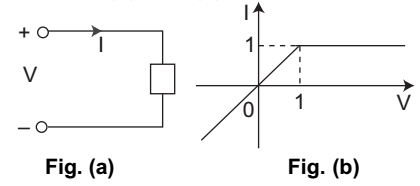
- The network element and V—L characteristics are shown in fig. (a) and (b). The element is—
-
View Hint View Answer Discuss in Forum
The given figure is non-linear because after 1 volt the output becomes constant.
Any element will be passive if the ratio V/I is positive any time, so the given output shown that the element in Passive.
Element will be bilateral if and only if the magnitude (i.e. V, or I) is same in both the direction. Here the given element is non-bilateral.Correct Option: D
The given figure is non-linear because after 1 volt the output becomes constant.
Any element will be passive if the ratio V/I is positive any time, so the given output shown that the element in Passive.
Element will be bilateral if and only if the magnitude (i.e. V, or I) is same in both the direction. Here the given element is non-bilateral.
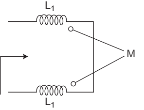
- The equivalent inductance of the network is—
-
View Hint View Answer Discuss in Forum
Since in one inductor current is leaving to dot and in other inductor current is entering to dot.
So L eq = L1 + L2 – 2MCorrect Option: A
Since in one inductor current is leaving to dot and in other inductor current is entering to dot.
So L eq = L1 + L2 – 2M
- A unit step u(t – 5) is applied to the RL network:
The current i is given by—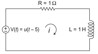
-
View Hint View Answer Discuss in Forum
I(∞) = I(∞) [1 – e–R/Lt]
I(∞) = V = u(t - 5) R 1
= u(t – 5) [1 – e–1/1t]
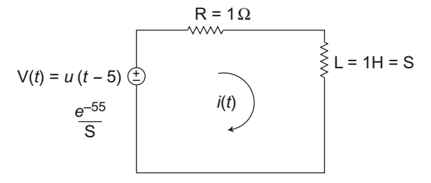
Alternative Method In frequency domaine–5s =I(s) + I(s) s s
.............. (i)I(s) = e –5s (s + 1)s I(s) = e–5s 
1 - 20 
s 1 + s
or i(t) = [1 – e–t] u [t – 5]
Hence alternative (C) is the correct choice.

Correct Option: C
I(∞) = I(∞) [1 – e–R/Lt]
I(∞) = V = u(t - 5) R 1
= u(t – 5) [1 – e–1/1t]
Alternative Method In frequency domaine–5s =I(s) + I(s) s s
.............. (i)I(s) = e –5s (s + 1)s I(s) = e–5s 1 - 20 s 1 + s
or i(t) = [1 – e–t] u [t – 5]
Hence alternative (C) is the correct choice.
Direction: A coil of inductance 10 H and resistance 40 Ω is connected as shown in the figure. After the switch S has been in contact with point 1 for a very long time, it is moved to poin 2 at t = 0.
- For the value of obtained in (a), the time taken for 95% of the stored energy to be dissipated is close to—
-
View Hint View Answer Discuss in Forum
= L Req = L = 10 Req 60 = 1 0·15 sec 6
Req = 20 + 40
= 60Ω
Correct Option: B
= L Req = L = 10 Req 60 = 1 0·15 sec 6
Req = 20 + 40
= 60Ω

