Power systems miscellaneous
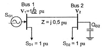
- For the system shown below, SD1 and SD2 are complex power demands at bus 1 and bus 2 respectively. If |V2| = 1 pu, the VAR rating of the capacitor (QG2) connected at bus 2 is
-
View Hint View Answer Discuss in Forum
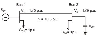
Current flowing from Bus 1 to Bus 2,I = V1 - V2 = - [1 - cosθ - jsinθ]2j z
S1 [power deliverd at Bus 1] = V1 I* = 2j [1 – cosθ + jsinθ]
Given, 2 sinθ = 1 = SD1
θ = 30°
S2 [power received at Bus 2] = V2 I*
= 2j [cosθ +j sinθ].[(1– cosθ) + j sinθ]
= 2j [1– cosθ) – 2 sinθ
&rdrr;
Reactive power.
VAR ratio of the capacitor QG2 at Bus (2) is,
Q = 2 [1 – cosθ]
Q = 2 [1 – cos 30°] = 0.268 p.u.Correct Option: B
Current flowing from Bus 1 to Bus 2,I = V1 - V2 = - [1 - cosθ - jsinθ]2j z
S1 [power deliverd at Bus 1] = V1 I* = 2j [1 – cosθ + jsinθ]
Given, 2 sinθ = 1 = SD1
θ = 30°
S2 [power received at Bus 2] = V2 I*
= 2j [cosθ +j sinθ].[(1– cosθ) + j sinθ]
= 2j [1– cosθ) – 2 sinθ
&rdrr;
Reactive power.
VAR ratio of the capacitor QG2 at Bus (2) is,
Q = 2 [1 – cosθ]
Q = 2 [1 – cos 30°] = 0.268 p.u.
- The sequence components of the fault current are as follows: Ipositive = j1.5 pu, I negative = – j0.5 pu, Izero = – j1 pu. The type of fault in the system is
-
View Hint View Answer Discuss in Forum
Given, Ia1 = j 1.5 p.u.
Ia2 = – j 0.5 p.u. and, 
Ia 
= 1 1 1 Ia0 Ib 1 α² α Ia1 Ic 1 α α² Ia2
Ia0 = – j 1.0 p.u.
then, Ia = Ia1 + Ia2 + Ia0 = 0.
In case of LLG faults at terminal b, c, the conditions at the faults are characterized by Vb = 0, Vc = 0, Ia = 0, as shown in figure also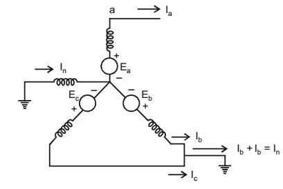
Correct Option: C
Given, Ia1 = j 1.5 p.u.
Ia2 = – j 0.5 p.u. and, Ia = 1 1 1 Ia0 Ib 1 α² α Ia1 Ic 1 α α² Ia2
Ia0 = – j 1.0 p.u.
then, Ia = Ia1 + Ia2 + Ia0 = 0.
In case of LLG faults at terminal b, c, the conditions at the faults are characterized by Vb = 0, Vc = 0, Ia = 0, as shown in figure also
- A two-phase load draws the following phase currents: i1 (t) = Im sin(ωt – φ1 ), i2 (t) = Im cos(ωt – φ2). These currents are balanced if φ1 is equal to
-
View Hint View Answer Discuss in Forum
i1 (t) = Im sin (ωt – φ1)
= Im cos [90° – (ωt – φ1)
= Im cos(°t – φ1 – 90°)
i2(t) = Im cos(ωt – φ2)
Angle difference between two currents should be – 180° (or) 180° for balanced
– φ1 + φ2 – 90°= – 180° ⇒ φ1 = 90° + φ2Correct Option: D
i1 (t) = Im sin (ωt – φ1)
= Im cos [90° – (ωt – φ1)
= Im cos(°t – φ1 – 90°)
i2(t) = Im cos(ωt – φ2)
Angle difference between two currents should be – 180° (or) 180° for balanced
– φ1 + φ2 – 90°= – 180° ⇒ φ1 = 90° + φ2
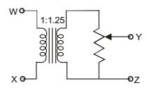
- The following arrangement consists of an ideal transformer and an attenuator which attenuates by a factor of 0.8. An ac voltage Vwx1 = l00V is applied across WX to get an open circuit voltage Vyz1, across YZ. Next, an ac voltageVyz2 = 100V is applied across YZ to get an open circuit voltage Vwx2 across WX. Then, Vyz1 VWX1/VWX2/VYZ2 are respectively.
-
View Hint View Answer Discuss in Forum
1st case :
Vwx1 = 100 VSo, Vy'z1 = M2 Vwx1 = 1.25 × 100 = 125V M1
∴ Vy'z1 = Vy'z1 × x = 125 × 0.8 = 100 v.
∴ Vyz1 /Vwx1 = 100/100
2nd case :
Vyz2 = 100 V∴ Vy't2 = 100 = 100 = 125 v α 0.8 Now, Vwx2 = M1 Vy'z2 = 1 × 125 = 100 v M2 1.25
∴ Vwx2/Vyz2 = 100/100
Vwx2 = 100VCorrect Option: B
1st case :
Vwx1 = 100 VSo, Vy'z1 = M2 Vwx1 = 1.25 × 100 = 125V M1
∴ Vy'z1 = Vy'z1 × x = 125 × 0.8 = 100 v.
∴ Vyz1 /Vwx1 = 100/100
2nd case :
Vyz2 = 100 V∴ Vy't2 = 100 = 100 = 125 v α 0.8 Now, Vwx2 = M1 Vy'z2 = 1 × 125 = 100 v M2 1.25
∴ Vwx2/Vyz2 = 100/100
Vwx2 = 100V
- Two magnetically uncoupled inductive coils have Q factors q1 and q2 at the chosen operating frequency. Their respective resistances are R1 and R2. When connected in series, their effective Q factor at the same operating frequency is
-
View Hint View Answer Discuss in Forum
q1 = WL1 ⇒ L1 = q1R1 ; q2 = WL2 R1 W R2
when connected in series
Leq = L1 + L2,qeq = WLeq = WL1WL2 = q1R1 + q2R2 Req R1 + R2 R1 + R2 Correct Option: C
q1 = WL1 ⇒ L1 = q1R1 ; q2 = WL2 R1 W R2
when connected in series
Leq = L1 + L2,qeq = WLeq = WL1WL2 = q1R1 + q2R2 Req R1 + R2 R1 + R2

