Power systems miscellaneous
- Single line diagram of a 4-bus single source distribution system is shown below. Branches e1, e2, e3 and e4 have equal impedances. The load current values indicated in the figure are in per unit.
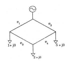
Distribution company’s policy requires radial system operation with minimum loss. This can be achieved by opening of the branch
-
View Hint View Answer Discuss in Forum
Let impedence of each branch be R. On removing e1 1
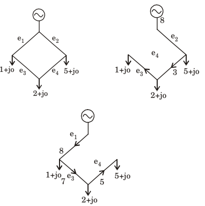
∴ Losses = 8²R + 3²R + 1²R = 74 R Simlary on removing e2
∴ Losses = 8²R + 7²R + 5²R = 138 R Simlary on removing e3
∴ Losses = 1²R + 7²R + 2²R = 54 R Simlary on removing e4
∴ Losses = 3²R + 2²R + 5²R = 38 R.
So on removing bus e4 losses are minimum, so correct of option is (d).Correct Option: D
Let impedence of each branch be R. On removing e1 1
∴ Losses = 8²R + 3²R + 1²R = 74 R Simlary on removing e2
∴ Losses = 8²R + 7²R + 5²R = 138 R Simlary on removing e3
∴ Losses = 1²R + 7²R + 2²R = 54 R Simlary on removing e4
∴ Losses = 3²R + 2²R + 5²R = 38 R.
So on removing bus e4 losses are minimum, so correct of option is (d).
- A lossless single machine infinite bus power system is shown below.
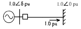
The synchronous generator transfers 1.0 per unit of power to the infinite bus. Critical clearing time of circuit breaker is 0.28 s. If another identical synchronous generator is connected in parallel to the existing generator and each generator is scheduled to supply 0.5 per unit of power. Then the critical clearing time of the circuit breaker will
-
View Hint View Answer Discuss in Forum
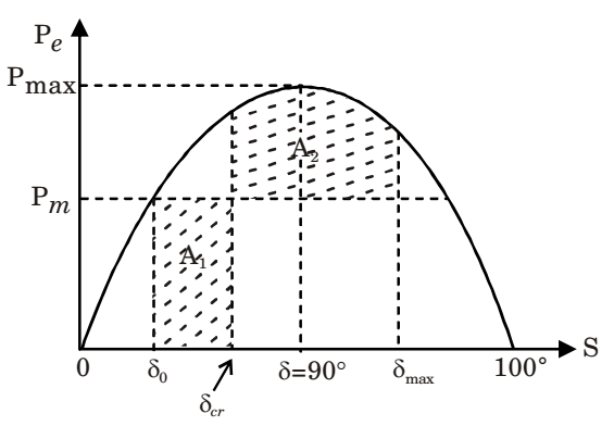
δcr = critical clearing angle
δmax = π – δ0
By equal area criterion, A1 = A2
⇒ Pm [δcr – δ0]
δcr = cos-1 [(π - 2δ0) sinδ0 - cosδ0]
and critical clearing time,tcr = 
24(δr - δ0) 
1/2 ..............(A) πƒPm
when one alternator is connected to the bus,
Pm1 = Pe1 = 1p.u.
When two alternator are connected in parallel, we get
Pe2 = Pm2 = 0.5 p.u.
By equation (A),tcr ∝ 1 √Pm tcr1 = √ Pm2 tcr2 Pm1 tcr1 = tcr2 Pm1 Pm2
= 0.28&dadic;2 = 0.396 secCorrect Option: B
δcr = critical clearing angle
δmax = π – δ0
By equal area criterion, A1 = A2
⇒ Pm [δcr – δ0]
δcr = cos-1 [(π - 2δ0) sinδ0 - cosδ0]
and critical clearing time,tcr = 24(δr - δ0) 1/2 ..............(A) πƒPm
when one alternator is connected to the bus,
Pm1 = Pe1 = 1p.u.
When two alternator are connected in parallel, we get
Pe2 = Pm2 = 0.5 p.u.
By equation (A),tcr ∝ 1 √Pm tcr1 = √ Pm2 tcr2 Pm1 tcr1 = tcr2 Pm1 Pm2
= 0.28&dadic;2 = 0.396 sec
- A logssless transmission line having Sure Impedance Loading (SIL) of 2280 MW is provided with a uniformly distributed series capacitive compensation of 30%. Then, SIL of the compensated transmission line will be
-
View Hint View Answer Discuss in Forum
There will not be any effect on active power of capacitve compensation
∴ SIL = 2280 MW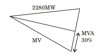
Alternately
Series reactance after series compensationZC2 = jωL - 1 = jωL 
1 - 1 
= jωL 1 - Xse jωCse Ω²LCse XL
The ratio, γ = Xse/XL se is called degree of series compensation.
Without compensation,(SIL)1 = V² , ZC = jωL Zc1
With series compensation,(SIL)² = V² Zc2 (SIL)2 = (SIL)1 × = Zc1 Zc2 = (SIL)1 √1 - γ = 2280 √1 - 0.3
= 2725 MWCorrect Option: B
There will not be any effect on active power of capacitve compensation
∴ SIL = 2280 MW
Alternately
Series reactance after series compensationZC2 = jωL - 1 = jωL 1 - 1 = jωL 1 - Xse jωCse Ω²LCse XL
The ratio, γ = Xse/XL se is called degree of series compensation.
Without compensation,(SIL)1 = V² , ZC = jωL Zc1
With series compensation,(SIL)² = V² Zc2 (SIL)2 = (SIL)1 × = Zc1 Zc2 = (SIL)1 √1 - γ = 2280 √1 - 0.3
= 2725 MW
- Voltage phasors at the two terminals of a transmissi on line of length 70 k m have a magnitude of 1.0 per unit but are 180 degrees out of phase. Assuming that the maximum load current in the line is 1 5 th of minimum 3-phase fault current, which one of the following transmission line protection schemes will NOT pick up for this condition?
-
View Hint View Answer Discuss in Forum
Distance protection using mho relays with zone – 1 set to 80% of line impedance will not provide protection.
Correct Option: A
Distance protection using mho relays with zone – 1 set to 80% of line impedance will not provide protection.
- It is desired to measure parameters of 230 V 115 V, 2 kVA, single-phase transformer. The following wattmeters are available in a laboratory:
W1 : 250V, 10 A, Low Power Factor
W2 : 250 V, 5 A Low Power Factor
W3 : 150 V, 10 A, High Power Factor
W4 : 150 V, 5 A, High Power Factor
The wattmeters used in open circuit test and short circuit test of the transformer will respectively be
-
View Hint View Answer Discuss in Forum
Open Circuit Test.
On L.V. side, rated voltage applied = 115 V
On L.V. side, current = 2 to 10% of rated current= 5 × 2000 = 0.869 A 100 115
A Since power consumed is less, so low power factor is used.
From available wattmeter,
W2 : 250 V, 5A. LPF used
Short Circuit Test
On H.V. side, rated current applied= 2000 = 8.69A 230
A and, applied voltage = 5 to 15% of rated Voltage.= 10 × 230 = 23V 100
Hight power is consumed, so H.P.F used. From available wattmeter, W3: 150 V, 10A. HDF
Hence answer is W2 and W3.Correct Option: D
Open Circuit Test.
On L.V. side, rated voltage applied = 115 V
On L.V. side, current = 2 to 10% of rated current= 5 × 2000 = 0.869 A 100 115
A Since power consumed is less, so low power factor is used.
From available wattmeter,
W2 : 250 V, 5A. LPF used
Short Circuit Test
On H.V. side, rated current applied= 2000 = 8.69A 230
A and, applied voltage = 5 to 15% of rated Voltage.= 10 × 230 = 23V 100
Hight power is consumed, so H.P.F used. From available wattmeter, W3: 150 V, 10A. HDF
Hence answer is W2 and W3.

