Power systems miscellaneous
- An isolated 50 Hz synchronous generator is rated at 15 MW which is also the maximum continuous power limit of its prime mover. It is equipped with a speed governor with 5% droop. Initially, the generator is feeding three loads of 4 MW each at 50 Hz. One of these loads is programmed to trip permanently if the frequency falls below 48 Hz. If an additional load of 3.5 MW is connected, then frequency will settle down to
-
View Hint View Answer Discuss in Forum

From the diagram we have,⇒ 0.05ƒ = 15 ƒ - 50 P1 ⇒ 0.05ƒ = 15 ƒ - 50 12
⇒ ƒ = 52.083
Now, the new load is, P' = 11.5 MW. Then,⇒ 52.083 - ƒ' = 11.5 25.083 - 50 12 ⇒ 52.083 - ƒ' = 2.08 × 11.05 12
⇒ ƒ' = 50.083 HzCorrect Option: C
From the diagram we have,⇒ 0.05ƒ = 15 ƒ - 50 P1 ⇒ 0.05ƒ = 15 ƒ - 50 12
⇒ ƒ = 52.083
Now, the new load is, P' = 11.5 MW. Then,⇒ 52.083 - ƒ' = 11.5 25.083 - 50 12 ⇒ 52.083 - ƒ' = 2.08 × 11.05 12
⇒ ƒ' = 50.083 Hz
- A 230 V (phase), 50 Hz, three - phase, 4 – wire system has a phase sequence ABC. A unity power - factor load of 4 kW is connected between phase A and neutral N. It is desired to achieve zero neutral current through the use of a pure inductor and a pure capacitor in the other two phase. The value of inductor and capacitor is
-
View Hint View Answer Discuss in Forum

Inductor is connected in phase-B and capacitor is connected in phase-C
IB lagging VBN by 90°.
IC leading VCN by 90°.
VAN = 230° ∠0° [VAN is reference phasor)
VBN = 230° ∠– 120
VCN = 230° ∠– 240
Given, IA is drawn at unity pf.IA = P = 4 × 10³ = 17.4∠0° VANcosφ 230
The current into the central will be zero
IB = IC
as IA = IBcos60 + IC cos60
= 2IB sin 60B = √3IB⇒ IB = IC = IA = 17.4 amp = 10.05 A √3 √3 as |IB| = | VBN | = 230 ωL (314)L ⇒ L = 230 = 72.86 mH 314 × 10.05
and |LC| = |CCN|. ωC = (230) × 314 × C⇒ C = 10.05 = 139.08 uf. 230 × 314 Correct Option: B
Inductor is connected in phase-B and capacitor is connected in phase-C
IB lagging VBN by 90°.
IC leading VCN by 90°.
VAN = 230° ∠0° [VAN is reference phasor)
VBN = 230° ∠– 120
VCN = 230° ∠– 240
Given, IA is drawn at unity pf.IA = P = 4 × 10³ = 17.4∠0° VANcosφ 230
The current into the central will be zero
IB = IC
as IA = IBcos60 + IC cos60
= 2IB sin 60B = √3IB⇒ IB = IC = IA = 17.4 amp = 10.05 A √3 √3 as |IB| = | VBN | = 230 ωL (314)L ⇒ L = 230 = 72.86 mH 314 × 10.05
and |LC| = |CCN|. ωC = (230) × 314 × C⇒ C = 10.05 = 139.08 uf. 230 × 314
- Consider the two power systems shown in Fig (a) below, which are initi ally not interconnected, and are operating in steady state at t he same frequency. Separate loadflow solutions are computed individually for the two systems, corresponding to this scenario. The bus voltage phasors so obtained are indicated on Fig (a). These two isolated systems are now interconnected by a short transmission line as shown in Fig (b), and it is found that P1 = P2 = Q1 = Q2 = 0

The bus voltage phase angular difference between generator bus X and generator bus Y after the interconnection is
-
View Hint View Answer Discuss in Forum
NA
Correct Option: A
NA
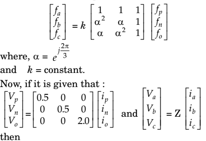
- Suppose we define a sequence transformation between “a-b-c” and “p-n-o” variables as follows:
-
View Hint View Answer Discuss in Forum
NA
Correct Option: B
NA
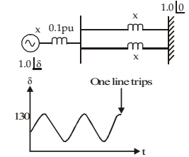
- Consider a synchronous generator connected to an infinite bus by two identical parallel transmission lines. The transient reactance x of the generator is 0.1 pu and the mechanical power input to it is constant at 1.0 pu. Due to some pr evious distur bance, the rotor angle (δ) is undergoing an undamped oscillation, with the maximum value of δ(t) equal to 130°. One of the parallel lines trips due to relay maloperation at an instant when δ(t) = 130° as shown in the figure given below. The maximum value of the per unit line reactance, x, such that the system does not lose synchronism subsequent to this tripping is
-
View Hint View Answer Discuss in Forum
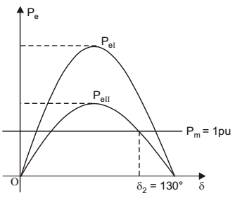
Pel = EƒVt sinδ, X X + 0.1 X1 2 PeII = EƒVt sinδ, when tripping occurs X2
At δ1 = δ2
PeII = Pm X2 = X + 0.⇒ EƒVt sinδ2 = 1 X2
⇒ sin 130° = X2
⇒ X2 = 0.76
⇒ X = X2 – 0.1 = 0.66Correct Option: C
Pel = EƒVt sinδ, X X + 0.1 X1 2 PeII = EƒVt sinδ, when tripping occurs X2
At δ1 = δ2
PeII = Pm X2 = X + 0.⇒ EƒVt sinδ2 = 1 X2
⇒ sin 130° = X2
⇒ X2 = 0.76
⇒ X = X2 – 0.1 = 0.66

