Power systems miscellaneous
- Match the items in List-I with the items in List-II and select the correct answer using the codes given below the lists.
List I (To) List II (Use) A. Improve power factor 1. Shunt reactor B. Reduce the current ripples 2. Shunt capacitor C. Increase the power 3. Series capacitor flow in line D. Reduce the Ferranti effect 4. Series reactor
Codes:
-
View Hint View Answer Discuss in Forum
Improve power factor – shunt capacitor Reduce the current ripples – series reactor Increase the power flow in line – series capacitor Reduce the Ferranti effect – shunt reactor
Correct Option: B
Improve power factor – shunt capacitor Reduce the current ripples – series reactor Increase the power flow in line – series capacitor Reduce the Ferranti effect – shunt reactor
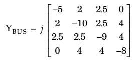
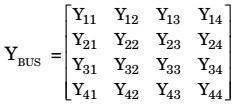
- For the Y-bus matrix of a 4-bus system given in per unit, the buses having shunt elements are
-
View Hint View Answer Discuss in Forum
Here, y11 = y10 + y12 + y13 + y14 = – 5j ....(i)
y22 = y20 + y22 + y23 + y24 = –10j ....(ii) y33 = y30 + y32 + y33 + y34 = –9 j ....(iii)
y44 = y40 + y42 + y43 + y44 = – 8j ...(iv) y12 = y21 = – y12 = 2j
y13 = y31 = – y13 = 2.5 j
y14 = y41 = – y10 = 0j
y23 = y32 = – y23 = 2.5 j
y24 = y42 – y24 = 4j
From equation (i),
y10 = y11 – y12 – y13 – y14
y10 = – 5j + 2j + 2.5j + 0j = – 0.5j
From equation (ii)
y20 = y22 – y12 – y23 – y24
= – 10j + 2 j + 2.5j + j = – 1.5 j
From equation (iii)
y30 = y33 – y31 – y32 – y34
= – 9j + 2.5j + 2.5j + j4 = 0
From equation (iv)
y40 = y44 – y41 – y42 – y43
= – 8j – 0 + 4j + 4j = 0
Hence obviously branches (1) and (2) behaves as shunt elements.Correct Option: C
Here, y11 = y10 + y12 + y13 + y14 = – 5j ....(i)
y22 = y20 + y22 + y23 + y24 = –10j ....(ii) y33 = y30 + y32 + y33 + y34 = –9 j ....(iii)
y44 = y40 + y42 + y43 + y44 = – 8j ...(iv) y12 = y21 = – y12 = 2j
y13 = y31 = – y13 = 2.5 j
y14 = y41 = – y10 = 0j
y23 = y32 = – y23 = 2.5 j
y24 = y42 – y24 = 4j
From equation (i),
y10 = y11 – y12 – y13 – y14
y10 = – 5j + 2j + 2.5j + 0j = – 0.5j
From equation (ii)
y20 = y22 – y12 – y23 – y24
= – 10j + 2 j + 2.5j + j = – 1.5 j
From equation (iii)
y30 = y33 – y31 – y32 – y34
= – 9j + 2.5j + 2.5j + j4 = 0
From equation (iv)
y40 = y44 – y41 – y42 – y43
= – 8j – 0 + 4j + 4j = 0
Hence obviously branches (1) and (2) behaves as shunt elements.
- For a fixed value of complex power flow in a transmissi on line having a sending end voltage V, the real powerloss will be proportional to
-
View Hint View Answer Discuss in Forum
S = P + jQ = VI (cosφ + j sinφ) = VIejφ
P = I²R = 
S 
² R = S²R × 1 Vejφ Ve2jφ V²
Alternately
Complex power,
VI* = P + jQ (taking V reference).∴ I* = P + jQ V I* = P - jQ V I = √P² + Q² V
∴ Real power loss = I²RI = P² + Q² R V²
But (P² + Q² × R) = constant∴ Power loss ∝ 1 V² 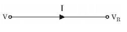
Correct Option: C
S = P + jQ = VI (cosφ + j sinφ) = VIejφ
P = I²R = S ² R = S²R × 1 Vejφ Ve2jφ V²
Alternately
Complex power,
VI* = P + jQ (taking V reference).∴ I* = P + jQ V I* = P - jQ V I = √P² + Q² V
∴ Real power loss = I²RI = P² + Q² R V²
But (P² + Q² × R) = constant∴ Power loss ∝ 1 V²
- Out of the following plant categories
(i) Nuclear
(ii) Run-of-river
(iii) Pump Storage
(iv) Diesel the base load power plants are
-
View Hint View Answer Discuss in Forum
NA
Correct Option: C
NA
- For the power system shown in the figure below, specifications of the components are following:
G1: 25 kV, 100 MVA, X = 9%
G2: 25 kV, 100 MVA, X = 9%
T1: 25 kV/ 220 kV, 90 MVA X = 12%
T2: 25 kV/25 kV, 90 MVA, X = 12%
Line 1: 220 kV, X = 150 ohms
Choose 25 kV as the base voltage at the generator G1, and 200 MVA as the MVA base. The impedance diagram is
-
View Hint View Answer Discuss in Forum

Base voltage = 25kV,
Base MVA = 200 MVA
Generator G1, G2XG1 = XG2 = 0.9 × 200 . 25 ² = j0.18 100 25 Xr1 = 0.12 × 200 . 25 ² = j0.27 90 25
For line 1, VL = 220 kV∴ XLine = 150 * 220 = 0.62 (220)² 
Correct Option: B
Base voltage = 25kV,
Base MVA = 200 MVA
Generator G1, G2XG1 = XG2 = 0.9 × 200 . 25 ² = j0.18 100 25 Xr1 = 0.12 × 200 . 25 ² = j0.27 90 25
For line 1, VL = 220 kV∴ XLine = 150 * 220 = 0.62 (220)²

