-
For the power system shown in the figure below, specifications of the components are following:
G1: 25 kV, 100 MVA, X = 9%
G2: 25 kV, 100 MVA, X = 9%
T1: 25 kV/ 220 kV, 90 MVA X = 12%
T2: 25 kV/25 kV, 90 MVA, X = 12%
Line 1: 220 kV, X = 150 ohms
Choose 25 kV as the base voltage at the generator G1, and 200 MVA as the MVA base. The impedance diagram is
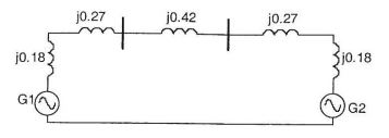
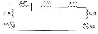
Correct Option: B

Base voltage = 25kV,
Base MVA = 200 MVA
Generator G1, G2
| XG1 = XG2 = 0.9 × |  |  | . | | | ² | = j0.18 | ||
| 100 | 25 |
| Xr1 = 0.12 × | | | . | | | ² | = j0.27 | ||
| 90 | 25 |
For line 1, VL = 220 kV
| ∴ XLine = 150 * | = 0.62 | |
| (220)² |


