Physical electronics devices and ics miscellaneous
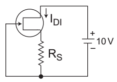
- The JFET in a circuit shown in figure has an IDSS = 10 mA and VP = – 5V. The value of the resistance RS for a drain current IDI = 6·4 mA is (select the nearest value)—
-
View Hint View Answer Discuss in Forum
The given circuit

Given, IDSS = 10 mA, Vp = – 5V, ID = 6·4 mA, RS =?
From given circuitID = IDSS 
1 - VGS 
2 Vp Or ID = 1 - VGS 2 IDSS Vp Or √6.4 = 1 - VGS 10 Vp or 0·8 = 1 – VGS Vp Or VGS = 0.2 Vp
or VGS = 0·2 Vp = 0·2 (– 5)
or VGS = – 1 V
Since VGS = – ID RS
or – 1 = – 6·4 mA × RSor RS = 1 = 156·25 Ω 6·4 × 10–3
or RS ≈ 150 Ω
Hence alternative (A) is the correct choice.Correct Option: A
The given circuit
Given, IDSS = 10 mA, Vp = – 5V, ID = 6·4 mA, RS =?
From given circuitID = IDSS 1 - VGS 2 Vp Or ID = 1 - VGS 2 IDSS Vp Or √6.4 = 1 - VGS 10 Vp or 0·8 = 1 – VGS Vp Or VGS = 0.2 Vp
or VGS = 0·2 Vp = 0·2 (– 5)
or VGS = – 1 V
Since VGS = – ID RS
or – 1 = – 6·4 mA × RSor RS = 1 = 156·25 Ω 6·4 × 10–3
or RS ≈ 150 Ω
Hence alternative (A) is the correct choice.
- An n-channel JFET has a pinch-off voltage of VP = – 5V, VDS (max) = 20V and gm = 2 mA/V. The minimum ‘ON’ resistance is achieved in the JFET for—
-
View Hint View Answer Discuss in Forum
NA
Correct Option: C
NA
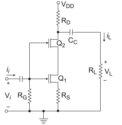
- For the series connected JFETs, IDSS = 8 mA and VPO = – 4V. If VDD = 15V, RD = 5 kΩ, RS = 2 kΩ and RG = 1 MΩ, find VDSQ.
-
View Hint View Answer Discuss in Forum
The given figure

From above circuit arrangement, we observed that VGSQ2 = VGSQ1 – VDSQ1
But IDQ1 = IDQ2
Since VGSQ1 = VGSQ2
therefore VDSQ1 = 0V Hence alternative (C) is the correct choice.Correct Option: C
The given figure
From above circuit arrangement, we observed that VGSQ2 = VGSQ1 – VDSQ1
But IDQ1 = IDQ2
Since VGSQ1 = VGSQ2
therefore VDSQ1 = 0V Hence alternative (C) is the correct choice.
-