Network theory miscellaneous
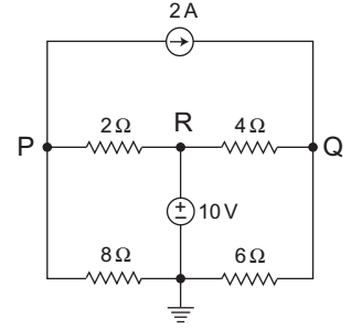
- For the circuit shown below, the potential difference between points P and Q is—
-
View Hint View Answer Discuss in Forum
The given circuit:
KCL at nodeVP - VR + VP - 0 + 2 = 0 2 8
orVP - 10 + VP + 2 = 0 2 8
orVP 1 + 1 = 3 2 8
orVP = 3 × 8 = 24 V 5 5
KCL at node QVQ - VR + VQ - 0 = 2 4 6 or VQ = VQ = 2 + 10 4 6 4
orVQ 1 + 1 = 8 + 10 4 6 4
orVQ = 18 × 24 = 54 4 10 5
Now,VQ -VQ 24 - 54 = -30 = -6V 5 5 5 Correct Option: C
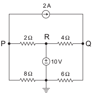
The given circuit:
KCL at nodeVP - VR + VP - 0 + 2 = 0 2 8
orVP - 10 + VP + 2 = 0 2 8
orVP 1 + 1 = 3 2 8
orVP = 3 × 8 = 24 V 5 5
KCL at node QVQ - VR + VQ - 0 = 2 4 6 or VQ = VQ = 2 + 10 4 6 4
orVQ 1 + 1 = 8 + 10 4 6 4
orVQ = 18 × 24 = 54 4 10 5
Now,VQ -VQ 24 - 54 = -30 = -6V 5 5 5
- A dc circuit shown below has a voltage V, a current source I and several resistors. A particular resistor R dissipates a power of 4W when V alone is active. The same resistor dissipates a power of 9W when I alone is active. The power dissipated by R when both sources are active will be—

-
View Hint View Answer Discuss in Forum
The given circuit:

Resistive network Applying superposition theorem (since here one energy source is acting at a time)
● When only voltage source is active:
V2/R = 4W = I2R
Let R = 1Ω
Assume I1 = I = 4 = 2A
● When only current source is active
I2R = 9W
or
I2 = 9W
Assume
I22 = I2 = 9
or
I2 = 3A
Since current flowing in both the case follow the same direction. Therefore, net current will add up.
So,
I = I1 + I2 = 2 + 3 = 5A
Now, the power dissipated by R when both sources are active will be:
P=I2R = 52.1 = 25W
Hence alternative (D) is the correct choice.Correct Option: D
The given circuit:
Resistive network Applying superposition theorem (since here one energy source is acting at a time)
● When only voltage source is active:
V2/R = 4W = I2R
Let R = 1Ω
Assume I1 = I = 4 = 2A
● When only current source is active
I2R = 9W
or
I2 = 9W
Assume
I22 = I2 = 9
or
I2 = 3A
Since current flowing in both the case follow the same direction. Therefore, net current will add up.
So,
I = I1 + I2 = 2 + 3 = 5A
Now, the power dissipated by R when both sources are active will be:
P=I2R = 52.1 = 25W
Hence alternative (D) is the correct choice.
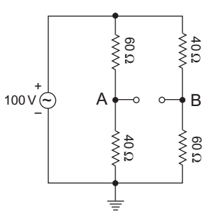
- What are the source voltage and source resistance, respectively for the Thevenin’s equivalent circuit as seen from the terminals indicated in the circuit given above?
-
View Hint View Answer Discuss in Forum
The given circuit:
Voltage at point A, VA = 40 × 100 = 40V 40 + 60 Voltage at point B, VB = 60 × 100 = 60V 40 + 60
Vth>/sub> = VBA = 60 – 40 = 20V
Equivalent circuit for calculating Rth is shown below: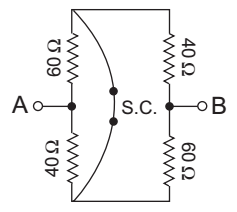
From figue, Rth = RAB = (60||40) + (40 ||60)
= 24 + 24 = 48Ω.Correct Option: B
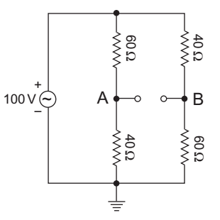
The given circuit:
Voltage at point A, VA = 40 × 100 = 40V 40 + 60 Voltage at point B, VB = 60 × 100 = 60V 40 + 60
Vth>/sub> = VBA = 60 – 40 = 20V
Equivalent circuit for calculating Rth is shown below:
From figue, Rth = RAB = (60||40) + (40 ||60)
= 24 + 24 = 48Ω.
- A network contains only independent current sources and resistors. If the values of all resistors are doubled, the values of node voltage—
-
View Hint View Answer Discuss in Forum
Let I1, I2, I3, … independent current sources are connected in parallel with resistors R1, R2, R3,…
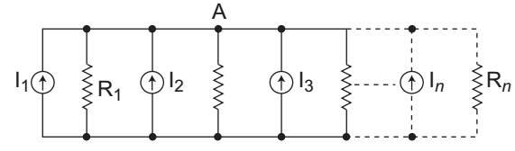
VA + VA + VA + .........= l1+l2+l3+..... R1 R2 R3
orVA 1 + 1 + 1 + .........= l1+l2+l3+..... R1 R2 R3
orVA = l1 + l2 + l3 +..... 1 + 1 + 1 R1 R2 R3
According to question, if the values of all resistors are doubled thenVA = l1 + l2 + l3 +..... 1 + 1 + 1 2R1 2R2 2R3
orVA = 2 × l1 + l2 + l3 +..... 1 + 1 + 1 +............... R1 R2 R3
Therefore the value of node voltage will become double.
Hence alternative (C) is the correct choice.Correct Option: C
Let I1, I2, I3, … independent current sources are connected in parallel with resistors R1, R2, R3,…
VA + VA + VA + .........= l1+l2+l3+..... R1 R2 R3
orVA 1 + 1 + 1 + .........= l1+l2+l3+..... R1 R2 R3
orVA = l1 + l2 + l3 +..... 1 + 1 + 1 R1 R2 R3
According to question, if the values of all resistors are doubled thenVA = l1 + l2 + l3 +..... 1 + 1 + 1 2R1 2R2 2R3
orVA = 2 × l1 + l2 + l3 +..... 1 + 1 + 1 +............... R1 R2 R3
Therefore the value of node voltage will become double.
Hence alternative (C) is the correct choice.
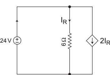
- Consider the circuit shown below. What is the power delivered by the 24V source?
-
View Hint View Answer Discuss in Forum
The given circuit:
From figure we conclude that the magnitude of current dependent source is 2 times that of 6Ω branch. It means resistance of dependent sources is half of the 6Ω, i.e., 3ΩI = V = 24 = 24 = 12A Req 3|| 6 2
Now, the power delivered by 24V source
= VI = 24 × 12 = 288W.
Alternative Method:
From figure, I = IR + 2IR = 3IR
Applying KVL in the input loop
24 = 6IR
or
IR = 4A
and
I = 3IR = 3 × 4 = 12A
Now, power delivered by 24V source is:
VI = 24 × 12 = 288W.Correct Option: D
The given circuit:
From figure we conclude that the magnitude of current dependent source is 2 times that of 6Ω branch. It means resistance of dependent sources is half of the 6Ω, i.e., 3ΩI = V = 24 = 24 = 12A Req 3|| 6 2
Now, the power delivered by 24V source
= VI = 24 × 12 = 288W.
Alternative Method:
From figure, I = IR + 2IR = 3IR
Applying KVL in the input loop
24 = 6IR
or
IR = 4A
and
I = 3IR = 3 × 4 = 12A
Now, power delivered by 24V source is:
VI = 24 × 12 = 288W.

