Network theory miscellaneous
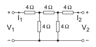
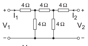
- The circuit shown in the above figure
1. is reciprocal
2. has Z11 = 2, Z22 = 2
3. has Z11 = 4, Z22 = 2
4. has Z11 = 0, Z22 = 2
Select the correct answer using the code given below—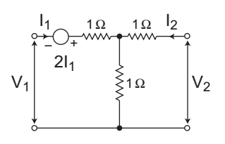
-
View Hint View Answer Discuss in Forum
The given circuit:

Applying KVL in the input side, we get
V1 = 2I1 + I1.1 + (I1 + I2).1
or
V1 = 4I1 + I2 …. . . .(i)
Again applying KVL in the output side, we get
V2 = I2.1 + (I1 + I2).1
or
V2 = I1 + 2I2. . . . …(ii)
From equation (i) and (ii):
Z11 = 4Ω, Z12 = 1Ω
Z21 = 1Ω, Z22 = 2Ω
For the network to be reciprocal
Z12 = Z21 (Here Z11 = Z12 = 1Ω)
So, network is reciprocal
and
Z11 = 4Ω, Z22 = 2Ω
Therefore, statements 1 and 3 are correct.
Hence alternative (A) is the correct choice.Correct Option: A
The given circuit:
Applying KVL in the input side, we get
V1 = 2I1 + I1.1 + (I1 + I2).1
or
V1 = 4I1 + I2 …. . . .(i)
Again applying KVL in the output side, we get
V2 = I2.1 + (I1 + I2).1
or
V2 = I1 + 2I2. . . . …(ii)
From equation (i) and (ii):
Z11 = 4Ω, Z12 = 1Ω
Z21 = 1Ω, Z22 = 2Ω
For the network to be reciprocal
Z12 = Z21 (Here Z11 = Z12 = 1Ω)
So, network is reciprocal
and
Z11 = 4Ω, Z22 = 2Ω
Therefore, statements 1 and 3 are correct.
Hence alternative (A) is the correct choice.
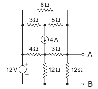
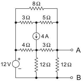
- What is the Thevenin resistance seen from the terminals AB of the circuit shown above in the figure?
-
View Hint View Answer Discuss in Forum
The given circuit:
The equivalent circuit for calculation of Rth is shown below—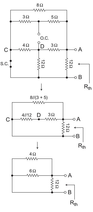
Now, from above figure1 = 1 + 1 + 1 Rth 4 6 12
or1 = 3 + 2 + 1 Rth 12
orRth = 12 = 2Ω 6
Hence alternative (A) is the correct choice.Correct Option: A
The given circuit:
The equivalent circuit for calculation of Rth is shown below—
Now, from above figure1 = 1 + 1 + 1 Rth 4 6 12
or1 = 3 + 2 + 1 Rth 12
orRth = 12 = 2Ω 6
Hence alternative (A) is the correct choice.
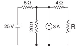
- What is the value of R required for maximum power transfer in the network shown above?
-
View Hint View Answer Discuss in Forum
The given network:
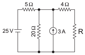
Let R = RL.
The value of R required for maximum power transfer in network is equivalent to net resistance as seen from the open load terminal (i.e. Thevenin’s resistance, Rth)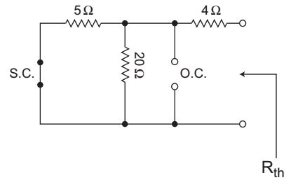
From above figure,
Rth = [5 || 20] + 4Ω = 4Ω + 4Ω = 8Ω
Hence alternative (C) is the correct choiceCorrect Option: C
The given network:
Let R = RL.
The value of R required for maximum power transfer in network is equivalent to net resistance as seen from the open load terminal (i.e. Thevenin’s resistance, Rth)
From above figure,
Rth = [5 || 20] + 4Ω = 4Ω + 4Ω = 8Ω
Hence alternative (C) is the correct choice
- What is the value of the parameter h12 for the 2-port network shown in the figure given above?
-
View Hint View Answer Discuss in Forum
The given network
We know thath12 = V1 /I1 = 0 V2
The given network can be modified as: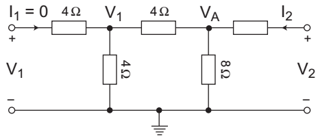
Applying KCL at node AVA- V2 + VA + VA- V1 = 0 4 8 4
orVA 
1 + 1 + 1 
= V2 + V1 4 8 4 4 4
or5 VA = V2 + V1 8 4 4
or5 VA = V2 + V1 …. . . . . . (i) 2
Again by applying potential divider ruleV1 = V1 × 4 = VA 2 2
or
VA = 2V1
Now5 .2V1 = V2 + V1 2
or
4 V1 = V2
orV1 = 1 = h12 = 0·250Ω V2 4
Hence alternative (C) is the correct choice.Correct Option: C
The given network
We know thath12 = V1 /I1 = 0 V2
The given network can be modified as:
Applying KCL at node AVA- V2 + VA + VA- V1 = 0 4 8 4
orVA 1 + 1 + 1 = V2 + V1 4 8 4 4 4
or5 VA = V2 + V1 8 4 4
or5 VA = V2 + V1 …. . . . . . (i) 2
Again by applying potential divider ruleV1 = V1 × 4 = VA 2 2
or
VA = 2V1
Now5 .2V1 = V2 + V1 2
or
4 V1 = V2
orV1 = 1 = h12 = 0·250Ω V2 4
Hence alternative (C) is the correct choice.
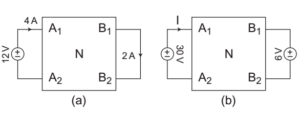
- The terminal volt-ampere conditions of a linear reciprocal network N are shown in the figure (a). What is the current I corresponding to the terminal conditions shown in the figure (b)?
-
View Hint View Answer Discuss in Forum
Current I1 due to 30V source only:
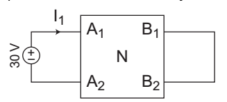
I1 = 4 × 30 = 10A (A2 to A1) 12
Current I2 due to 6V source is: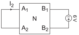
I2 = 2 × 6 = 1A (A2 to A1) 12
Total current, I = I1 + I2 = 10 + 1 = 11A
Hence alternative (D) is the correct choice.Correct Option: D
Current I1 due to 30V source only:
I1 = 4 × 30 = 10A (A2 to A1) 12
Current I2 due to 6V source is: I2 = 2 × 6 = 1A (A2 to A1) 12
Total current, I = I1 + I2 = 10 + 1 = 11A
Hence alternative (D) is the correct choice.

