Network theory miscellaneous
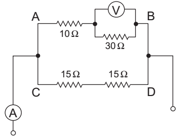
- For the circuit shown below, the voltage across 30Ω resistor is 45 volts. The reading of ammeter A will be—
-
View Hint View Answer Discuss in Forum
The given circuit:
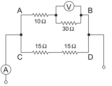
From figure,I30Ω = 45 = 1·5A 30
Voltage across 10Ω resistance is
= 1·5 × 10 = 15V
Now,
VAB = 15V + 45V = 60 V
Current in branchCD = 60V = 2A 30Ω
Now, current in ammeter
= 1·5 + 2 = 3·5 ACorrect Option: B
The given circuit:
From figure,I30Ω = 45 = 1·5A 30
Voltage across 10Ω resistance is
= 1·5 × 10 = 15V
Now,
VAB = 15V + 45V = 60 V
Current in branchCD = 60V = 2A 30Ω
Now, current in ammeter
= 1·5 + 2 = 3·5 A
- For a series RLC resonant circuit, which one of the following gives the impedance at the lower and upper half power frequencies, respectively?
-
View Hint View Answer Discuss in Forum
For a series RLC circuit, at lower half frequency current is 1/2 times and leading in nature whereas at upper half frequency current is 1/2 times and lagging in nature.
Correct Option: B
For a series RLC circuit, at lower half frequency current is 1/2 times and leading in nature whereas at upper half frequency current is 1/2 times and lagging in nature.
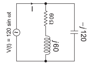
- For the a.c. circuit given below, what is the value of I?
-
View Hint View Answer Discuss in Forum
The given circuit:
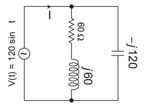
I = V = 120 Zeq (60 + j 60) || – 120j
orI = 120 60 (1 + j) × (– 120j) 60 (1 + j) – 120j
orI = 120 60 (1 + j) (– 120j) 60 (1 – j)
orI = (1 – j) j = j + 1 = 0 (1 + j) 1 + j
or
I = 0 + j 0
Hence alternative (D) is the correct choice.Correct Option: D
The given circuit:
I = V = 120 Zeq (60 + j 60) || – 120j
orI = 120 60 (1 + j) × (– 120j) 60 (1 + j) – 120j
orI = 120 60 (1 + j) (– 120j) 60 (1 – j)
orI = (1 – j) j = j + 1 = 0 (1 + j) 1 + j
or
I = 0 + j 0
Hence alternative (D) is the correct choice.
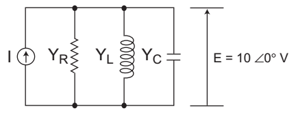
- In figure, the admittance values of the elements in siemens are YR = 0·5 + j0, YL = 0 – J1·5, YC = 0 + j0·3 respectively. The value of I as a phasor when the voltage E across the elements is 10 ∠ 0° V is—
-
View Hint View Answer Discuss in Forum
The given figure:

I = V Yeq
where, Yeq = YR + YL + YC
= 0·5 + j0 + 0 – j1·5 + 0·j 0·3
= 0·5 – j1·2
Now, I = 10 0° (0·5 + j1·2)
or
I = 5 – j12
Hence alternative (D) is the correct choice.Correct Option: D
The given figure:
I = V Yeq
where, Yeq = YR + YL + YC
= 0·5 + j0 + 0 – j1·5 + 0·j 0·3
= 0·5 – j1·2
Now, I = 10 0° (0·5 + j1·2)
or
I = 5 – j12
Hence alternative (D) is the correct choice.
- In the circuit shown in the given figure, power dissipated in the 5Ω resistor is—

-
View Hint View Answer Discuss in Forum
The given circuit:
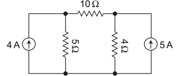
The circuit can be modified as shown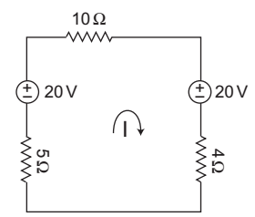
– 5I + 20 – 10 I – 20 – 4 I = 0
or
19 I = 0
or I = 0
Therefore, the power dissipated in 5Ω resistor is zero.Correct Option: A
The given circuit:
The circuit can be modified as shown
– 5I + 20 – 10 I – 20 – 4 I = 0
or
19 I = 0
or I = 0
Therefore, the power dissipated in 5Ω resistor is zero.

