Network theory miscellaneous
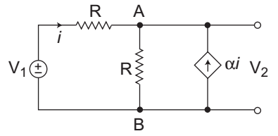
- Consider the circuit as shown below which has a current dependent current source. The value V2 /V1 is—
-
View Hint View Answer Discuss in Forum
The given circuit:
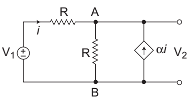
Applying KCL at node A, we getVA - V1 + VA = αi ........…(i) R R
From figure:VA = V2 and V1 - VA = i R
Now,V2 - V1 + V2 = α V1 - VA = i R R R
orV2 1 + 1 + α = α V1 + V1 R R R R R
orV2 2 + α = V1 α + 1 R R
orV2 = 1 + α V1 2 + α
Hence alternative (C) is the correct choice.Correct Option: C
The given circuit:
Applying KCL at node A, we getVA - V1 + VA = αi ........…(i) R R
From figure:VA = V2 and V1 - VA = i R
Now,V2 - V1 + V2 = α V1 - VA = i R R R
orV2 1 + 1 + α = α V1 + V1 R R R R R
orV2 2 + α = V1 α + 1 R R
orV2 = 1 + α V1 2 + α
Hence alternative (C) is the correct choice.
- The laplace transform of the waveform shown in the figure is
F(s) = 1 (1 + Ae-e + Be-4s + Ce-6s + De-8s) s2
What is the value of D?
-
View Hint View Answer Discuss in Forum
The given waveform:

Given, F(s) = 1 [1 + Ae–s + Be–4s + Ce–6s + De–8s] s2
The slope of D is 1/2 = 0·5
Hence alternative (C) is the correct choice.Correct Option: C
The given waveform:
Given, F(s) = 1 [1 + Ae–s + Be–4s + Ce–6s + De–8s] s2
The slope of D is 1/2 = 0·5
Hence alternative (C) is the correct choice.
- Which one of the following is the transfer function of an electrical low pass filter using R and C elements?
-
View Hint View Answer Discuss in Forum
The low pass filter using R and C components:

V0(s) = Vi(s) 1 Cs R + 1 Cs V0(s) = H(s) = 1 Vi(s) (1 + RCs)
Hence alternative (B) is the correct choice.Correct Option: B
The low pass filter using R and C components:
V0(s) = Vi(s) 1 Cs R + 1 Cs V0(s) = H(s) = 1 Vi(s) (1 + RCs)
Hence alternative (B) is the correct choice.
- In the circuit shown in the figure below, for what value of C will the current I be in phase with the sinusoidal source voltage Vs = sin 2t?

-
View Hint View Answer Discuss in Forum
The given circuit:

Given, Vs = sin 2t, means = 2 rad/sec.
In order to make the current I in phase with the sinusoidal source voltage, the imaginary part of the net impedance offered by the voltage source must be zero.
So,Zeq = 1 || (1 + j1) j C
orZeq = 1 × (1 + j) j2C 1 + (1 + j) j2C
orZeq = 1 × [1 + j] 2C 2C + j (2C - 1)
2C – 1 = 0 (Since Imaginary part must be zero)
or
C = 1/2 F
Hence alternative (B) is the correct choice.Correct Option: B
The given circuit:
Given, Vs = sin 2t, means = 2 rad/sec.
In order to make the current I in phase with the sinusoidal source voltage, the imaginary part of the net impedance offered by the voltage source must be zero.
So,Zeq = 1 || (1 + j1) j C
orZeq = 1 × (1 + j) j2C 1 + (1 + j) j2C
orZeq = 1 × [1 + j] 2C 2C + j (2C - 1)
2C – 1 = 0 (Since Imaginary part must be zero)
or
C = 1/2 F
Hence alternative (B) is the correct choice.
- In the circuit shown below, what is the voltage across 5Ω resistor i.e. (V1 – V2)

-
View Hint View Answer Discuss in Forum
The given circuit:

From figure, KCL at node 1V1 + V1 – V2 = 176 …. .......(i) 7 5
Again KCL at node 2V2 + V2 – V1 = 110 …. .......(i) 10 5
From equation (i) and (ii), we get
V1 = 1190V and V2 = 1160V
Now, V1 – V2 = 1190 – 1160 = 30VCorrect Option: B
The given circuit:
From figure, KCL at node 1V1 + V1 – V2 = 176 …. .......(i) 7 5
Again KCL at node 2V2 + V2 – V1 = 110 …. .......(i) 10 5
From equation (i) and (ii), we get
V1 = 1190V and V2 = 1160V
Now, V1 – V2 = 1190 – 1160 = 30V

