Network theory miscellaneous
- For the circuit shown below, the power absorbed by 2Ω resistor is—

-
View Hint View Answer Discuss in Forum
The given circuit:

From above figure we conclude that the current passing through 2Ω resistor is 3A.
So,
Power absorbed = I2R = 32 × 2 = 18W.Correct Option: C
The given circuit:
From above figure we conclude that the current passing through 2Ω resistor is 3A.
So,
Power absorbed = I2R = 32 × 2 = 18W.
- The effective inductance of the circuit shown below—

-
View Hint View Answer Discuss in Forum
The given circuit:
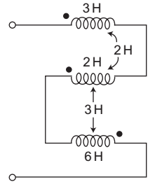
Leq = L1 + L2 + L3 – 2M12 + 2M23
where
L1 = 3H, L2 = 2H, L3 = 6H, M12 = 2H, M23 = 3H
Now,
Leq = 3H + 2H + 6H – 2 × 2H + 2 × 3H
or
Leq = 11H – 4H + 6H = 13H
Hence alternative (A) is the correct choice.Correct Option: A
The given circuit:
Leq = L1 + L2 + L3 – 2M12 + 2M23
where
L1 = 3H, L2 = 2H, L3 = 6H, M12 = 2H, M23 = 3H
Now,
Leq = 3H + 2H + 6H – 2 × 2H + 2 × 3H
or
Leq = 11H – 4H + 6H = 13H
Hence alternative (A) is the correct choice.
- The circuit shown below, will act as an ideal current source with respect to terminals A and B, when frequency is—

-
View Hint View Answer Discuss in Forum
= 1 rad/sec LC
or= 1 1 × 1 16
= 4 rad/sec.Correct Option: C
= 1 rad/sec LC
or= 1 1 × 1 16
= 4 rad/sec.
- For the circuit shown below, the power absorbed by 2Ω resistor and power delivered by 10V source will be—

-
View Hint View Answer Discuss in Forum
The given circuit:

From figure, 20 – 2I – 8 I – 10 = 0
or
I = 1A
Power absorbed by 2Ω resistor = I2R = 12 × 2 = 2W
Power delivered by 10V source = – VI = – 10 × 1 = – 10W
[Note: Here negative sign is taken because current is entering at the negative terminal of the 10V voltage source]
Hence alternative (C) is the correct choice.Correct Option: C
The given circuit:
From figure, 20 – 2I – 8 I – 10 = 0
or
I = 1A
Power absorbed by 2Ω resistor = I2R = 12 × 2 = 2W
Power delivered by 10V source = – VI = – 10 × 1 = – 10W
[Note: Here negative sign is taken because current is entering at the negative terminal of the 10V voltage source]
Hence alternative (C) is the correct choice.
- In the given figure, the Thevenin’s equivalent pair (voltage, impedance), as seen at the terminals P–Q, is given by—

-
View Hint View Answer Discuss in Forum
The given circuit:

Rth Calculation: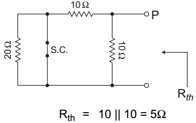
Rth = 10 || 10 = 5Ω
Vth Calculation:
I = 4V = 4V = 0.4 A Req 10Ω I1 = 0.4 × 20 = 0.2A 20 + 20
Vth = I1 × 10Ω = 0·2 × 10 = 2V
Hence alternative (A) is the correct choice.Correct Option: A
The given circuit:
Rth Calculation:
Rth = 10 || 10 = 5Ω
Vth Calculation:I = 4V = 4V = 0.4 A Req 10Ω I1 = 0.4 × 20 = 0.2A 20 + 20
Vth = I1 × 10Ω = 0·2 × 10 = 2V
Hence alternative (A) is the correct choice.

