Control systems miscellaneous
- In the signal flow graph of figure the gain C/R will be—

-
View Hint View Answer Discuss in Forum
By using Manson’s gain formula for signal flow graph.
Here,
P1 = 2 × 3 × 4 = 24
P2 = 5
Δ1 = 1
Δ2 = 1 – (– 3) = 4
Δ = 1 – (sum of individual loop T. F.) + (sum of loop transmittance products of all possible pairs)
= 1 – (– 2 – 3 – 4 – 5) + (– 2x – 4)
= 1 + 14 + 8
= 23T.F. = C = P1Δ1 + P2Δ2 R Δ = 24 × 1 + 5 × 4 23 = 44 23
Hence alternative (D) is the correct choice.
Correct Option: D
By using Manson’s gain formula for signal flow graph.
Here,
P1 = 2 × 3 × 4 = 24
P2 = 5
Δ1 = 1
Δ2 = 1 – (– 3) = 4
Δ = 1 – (sum of individual loop T. F.) + (sum of loop transmittance products of all possible pairs)
= 1 – (– 2 – 3 – 4 – 5) + (– 2x – 4)
= 1 + 14 + 8
= 23T.F. = C = P1Δ1 + P2Δ2 R Δ = 24 × 1 + 5 × 4 23 = 44 23
Hence alternative (D) is the correct choice.
- The transfer function θ0(s) θ1(s) of the block diagram is

-
View Hint View Answer Discuss in Forum
Apply same concept as discussed in sol. 136, we get.
Alternative approachT.F. = θ0(s) = G2G3G4 + H2G4 θ1(s) 1 + G2G3G4H1 + H1H2G4
Since, here there are two forward path i.e.,
P1 = G2G3G4
and P2 = H2G4
and two possible loops i.e.,
L1 = G2G3G4H1
and L2 = H1H2G4
Hence alternative (C) is the correct choice.
Correct Option: C
Apply same concept as discussed in sol. 136, we get.
Alternative approachT.F. = θ0(s) = G2G3G4 + H2G4 θ1(s) 1 + G2G3G4H1 + H1H2G4
Since, here there are two forward path i.e.,
P1 = G2G3G4
and P2 = H2G4
and two possible loops i.e.,
L1 = G2G3G4H1
and L2 = H1H2G4
Hence alternative (C) is the correct choice.
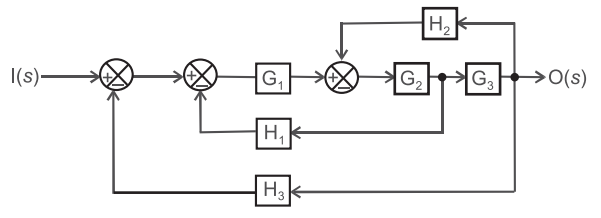
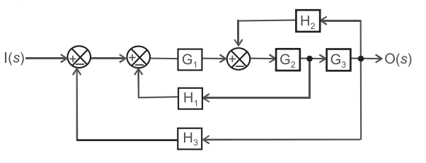
- The overall transfer function O(s)/I(s) is—

-
View Hint View Answer Discuss in Forum
In order to calculate the overall transfer function of such type of complex block diagram, use direct formula given below. Overall
T. F. = Sum of total forward path gain 1 + sum of all loops associated with the gain factors
Here, only one forward path = G1G2G3 Sum of all possible loops = G1G2H1 + G1G2G3H3 + G2G3H2 Hence,
O(s) = G1G2G3 I(s) 1 + G1G2H1 + G1G2G3H3 + G2G3H2
Hence alternative (C) is the correct choice.
Correct Option: C
In order to calculate the overall transfer function of such type of complex block diagram, use direct formula given below. Overall
T. F. = Sum of total forward path gain 1 + sum of all loops associated with the gain factors
Here, only one forward path = G1G2G3 Sum of all possible loops = G1G2H1 + G1G2G3H3 + G2G3H2 Hence,
O(s) = G1G2G3 I(s) 1 + G1G2H1 + G1G2G3H3 + G2G3H2
Hence alternative (C) is the correct choice.
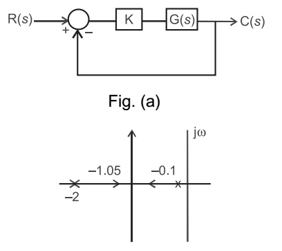
- Consider a closed loop system shown in figure (a) below. The root locus for it is shown in figure (b). The closed-loop transfer function for the system is—

-
View Hint View Answer Discuss in Forum
From root locus, the poles of G(s) lie at s = – 0·1 and s = – 2.
Hence we can have G(s) of the form KG(s) F= K (0·5s + 1) (10s + 1)
Hence the closed-loop transfer function= C(s) R(s) = KG(s) 1 + KG(s) H(s)
Since, H(s) = 1, we haveC(s) = KG(s) R(s) 1 + KG(s) = K/(0·5s + 1) (10s + 1) 1 + K/(0·5s + 1) (10s + 1) = K (0·5s + 1) (10s + 1) + K
Hence (D) is the correct choice.
Correct Option: D
From root locus, the poles of G(s) lie at s = – 0·1 and s = – 2.
Hence we can have G(s) of the form KG(s) F= K (0·5s + 1) (10s + 1)
Hence the closed-loop transfer function= C(s) R(s) = KG(s) 1 + KG(s) H(s)
Since, H(s) = 1, we haveC(s) = KG(s) R(s) 1 + KG(s) = K/(0·5s + 1) (10s + 1) 1 + K/(0·5s + 1) (10s + 1) = K (0·5s + 1) (10s + 1) + K
Hence (D) is the correct choice.
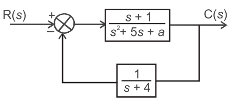
- 129. For what values of ‘a’ does the system shown in figure have a zero steady s`tate error (i.e. Lim t → ∞ e(t)) for a step input?

-
View Hint View Answer Discuss in Forum
From figure Since, E(s) = X(s) – Y(s).H(s)
or E(s) = X(s) – G(s) X(s).H(s) 1 + G(s) H(s) or E(s) = X(s) – 1 1 + G(s) H(s) 
∴ X(s) = 1 for step input 
s or E(s) = 1 
1 
s +1 (s + 1) × 1/(s2 + 5 + a)(s + 4)
Now, steady state error ess is
ess = t → ∞lim e(t) = t → ∞lim sE(s)
or ess = s → 0lim ·s 1 
1 
s +1 (s + 1) × 1/(s2 + 5 + a)(s + 4)
oror ess = 4a 4a + 1
for steady state error, ess to be zero,4a = 0 4a + 1
or
a = 0 Hence alternative (A) is the correct choice.
Correct Option: A
From figure Since, E(s) = X(s) – Y(s).H(s)
or E(s) = X(s) – G(s) X(s).H(s) 1 + G(s) H(s) or E(s) = X(s) – 1 1 + G(s) H(s) 
∴ X(s) = 1 for step input 
s or E(s) = 1 
1 
s +1 (s + 1) × 1/(s2 + 5 + a)(s + 4)
Now, steady state error ess is
ess = t → ∞lim e(t) = t → ∞lim sE(s)
or ess = s → 0lim ·s 1 
1 
s +1 (s + 1) × 1/(s2 + 5 + a)(s + 4)
oror ess = 4a 4a + 1
for steady state error, ess to be zero,4a = 0 4a + 1
or
a = 0 Hence alternative (A) is the correct choice.

