Control systems miscellaneous
- The transfer function of a system is 10/1 + s. When operated as a unity feedback system, the steady state error to a unit step input will be—
-
View Hint View Answer Discuss in Forum
T.F. = C(s) = 10 and H(s) = 1 R(s) 1 + s G(s) = 10 1 + G(s)H(s) 1 + s G(s) = 10 1 + G(s).1 1 + s
G(s) + SG(s) = 10 + 10 G(s)
G (s) [1 + s – 10] = 10G(s) = 10 s - 9
Also, we know that,E(s) = 1 R(s) 1 + G(s) H(s)
orE(s) = R(s) {1/s for unit step or} 1 + G(s) H(s) E(s) = 1/s 1 + 10/s - 9.1
orE(s) = (s - 9) (s + 1).s
Now,ess = s → 0Lim sE(s) = s → 0Lim s·(s – 9) = – 9 = -9 (s + 1).s 1 Correct Option: B
T.F. = C(s) = 10 and H(s) = 1 R(s) 1 + s G(s) = 10 1 + G(s)H(s) 1 + s G(s) = 10 1 + G(s).1 1 + s
G(s) + SG(s) = 10 + 10 G(s)
G (s) [1 + s – 10] = 10G(s) = 10 s - 9
Also, we know that,E(s) = 1 R(s) 1 + G(s) H(s)
orE(s) = R(s) {1/s for unit step or} 1 + G(s) H(s) E(s) = 1/s 1 + 10/s - 9.1
orE(s) = (s - 9) (s + 1).s
Now,ess = s → 0Lim sE(s) = s → 0Lim s·(s – 9) = – 9 = -9 (s + 1).s 1
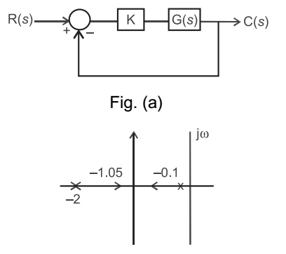
- Consider a closed loop system shown in figure (a) below. The root locus for it is shown in figure (b). The closed-loop transfer function for the system is—

-
View Hint View Answer Discuss in Forum
From root locus, the poles of G(s) lie at s = – 0·1 and s = – 2.
Hence we can have G(s) of the form KG(s) F= K (0·5s + 1) (10s + 1)
Hence the closed-loop transfer function= C(s) R(s) = KG(s) 1 + KG(s) H(s)
Since, H(s) = 1, we haveC(s) = KG(s) R(s) 1 + KG(s) = K/(0·5s + 1) (10s + 1) 1 + K/(0·5s + 1) (10s + 1) = K (0·5s + 1) (10s + 1) + K
Hence (D) is the correct choice.
Correct Option: D
From root locus, the poles of G(s) lie at s = – 0·1 and s = – 2.
Hence we can have G(s) of the form KG(s) F= K (0·5s + 1) (10s + 1)
Hence the closed-loop transfer function= C(s) R(s) = KG(s) 1 + KG(s) H(s)
Since, H(s) = 1, we haveC(s) = KG(s) R(s) 1 + KG(s) = K/(0·5s + 1) (10s + 1) 1 + K/(0·5s + 1) (10s + 1) = K (0·5s + 1) (10s + 1) + K
Hence (D) is the correct choice.
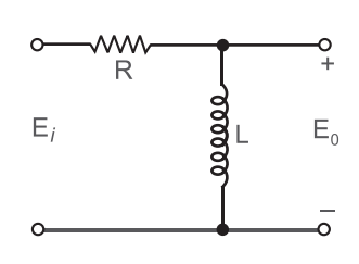
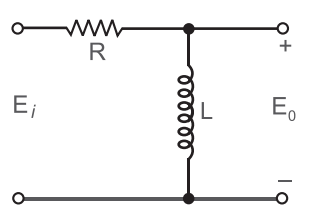
- The transfer function Eo (s)/Ei (s) of the circuit is—

-
View Hint View Answer Discuss in Forum
From given figure
E0(s) = Ls · Ei(s) R + Ls or E0(s) = Ls Ei(s) R + Ls or E0(s) = s Ei(s) s + (R/L) 
Correct Option: D
From given figure
E0(s) = Ls · Ei(s) R + Ls or E0(s) = Ls Ei(s) R + Ls or E0(s) = s Ei(s) s + (R/L) 
- The transfer function Eo(s)/Ei(s) of the network is

-
View Hint View Answer Discuss in Forum
KCL at node A, and apply Laplace transform
VA(s) – Ei(s) + VA .Cs + VA – E0(s) = 0 …(i) R R
[˙.˙ VB = Eo(s)]
KCL at node B.E0(s) + E0(s) – VA = 0 …(ii) 1/Cs R
from equation (ii)
VA= Eo(s) [RCS + 1] …(iii)
Now by using equations (i) and (iii) and on putting T = RC we getEo (s). [Ts + 1] = Ei(s) + E0(s) (Ts + 2)
oror Eo (s). 
Ts + 1 - 1 
= Ej(s) Ts + 2 (Ts + 2) or E0(s) = 1 Ej(s) T2s2 + 3Ts + 1 
Correct Option: C
KCL at node A, and apply Laplace transform
VA(s) – Ei(s) + VA .Cs + VA – E0(s) = 0 …(i) R R
[˙.˙ VB = Eo(s)]
KCL at node B.E0(s) + E0(s) – VA = 0 …(ii) 1/Cs R
from equation (ii)
VA= Eo(s) [RCS + 1] …(iii)
Now by using equations (i) and (iii) and on putting T = RC we getEo (s). [Ts + 1] = Ei(s) + E0(s) (Ts + 2)
oror Eo (s). 
Ts + 1 - 1 
= Ej(s) Ts + 2 (Ts + 2) or E0(s) = 1 Ej(s) T2s2 + 3Ts + 1 
- Consider the control system shown in the following figure and the statements given below.
1. The system is of second order.
2. Basically, the system is having positive feedback.
3. The system is of type 1.
4. The dimension of the output is not the same as that of the input. Of these statements—
-
View Hint View Answer Discuss in Forum
Here,
G(s) = 9 s (s + 3)
H (s) = – s2 9
T.F. of the given system= G(s) 1 + G(s) H(s) = 9/s(s + 3) 1 + {9/s(s + 3)}(– s2/9)
form, this we conclude that only statement 2 and 4 is correct.= 9 = 3 s2 + 3s – s2 s
Hence alternative (B) is the correct choice.
Correct Option: B
Here,
G(s) = 9 s (s + 3)
H (s) = – s2 9
T.F. of the given system= G(s) 1 + G(s) H(s) = 9/s(s + 3) 1 + {9/s(s + 3)}(– s2/9)
form, this we conclude that only statement 2 and 4 is correct.= 9 = 3 s2 + 3s – s2 s
Hence alternative (B) is the correct choice.

