Analog circuits miscellaneous
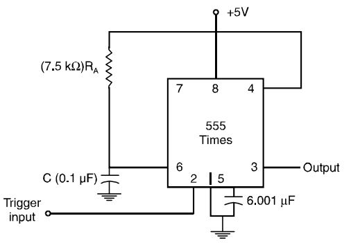
- The period of the output waveform for the circuit of figure shown, when triggered by a negative pulse is
-
View Hint View Answer Discuss in Forum
T = (1.1) RAC
= 1.1(7.5 × 10³) (0.1 × 10– 6) = 0.825 ms.Correct Option: B
T = (1.1) RAC
= 1.1(7.5 × 10³) (0.1 × 10– 6) = 0.825 ms.
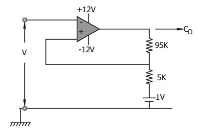
- What is the hysterisis voltage of the submitt trigger shown if Vsat = ± 10V ?
-
View Hint View Answer Discuss in Forum
Hysterisis voltage,
VH = 2 R2 V0 = 2 × 5 × 10 = 1 volt R1 + R2 100
Correct Option: C
Hysterisis voltage,
VH = 2 R2 V0 = 2 × 5 × 10 = 1 volt R1 + R2 100
- In the switcling circuit shown, RC time constant is much longer as compared to the time period of its input pulse signal. Vout of this circuit is of the form

-
View Hint View Answer Discuss in Forum
During ‘+’ ve cycle, diode turns ON and V0 = 0V. Between positive peaks, diode is OFF and V0 = 2Vin

Correct Option: B
During ‘+’ ve cycle, diode turns ON and V0 = 0V. Between positive peaks, diode is OFF and V0 = 2Vin

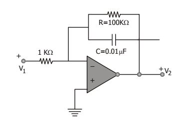
- The low frequency gain of the low pass filter shown in the given figure is
-
View Hint View Answer Discuss in Forum

V2 
= R . 1 V1 R1 RCs + 1 = 100 1 ≈ 100 10-3 j + 1 ∴ 20 log 
V2 
= 40 dB V1 Correct Option: D

V2 
= R . 1 V1 R1 RCs + 1 = 100 1 ≈ 100 10-3 j + 1 ∴ 20 log 
V2 
= 40 dB V1
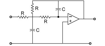
- The transfer function of a second order LP filter shown in the given figure is
-
View Hint View Answer Discuss in Forum
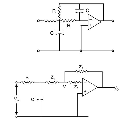
Using ∆ – Y conversion,Z1 = R2Cs 2RCs + 1 Z2 = R 2RCs + 1 Z3 = R 2RCs + 1
From the figure, using KCL, we haveV0 = 1 Vin R2C2s2 + 3RCs + 1
Correct Option: A

Using ∆ – Y conversion,Z1 = R2Cs 2RCs + 1 Z2 = R 2RCs + 1 Z3 = R 2RCs + 1
From the figure, using KCL, we haveV0 = 1 Vin R2C2s2 + 3RCs + 1

