Analog circuits miscellaneous
- In the differentiating circuit given in the figure, function of R1 is to

-
View Hint View Answer Discuss in Forum
NA
Correct Option: B
NA
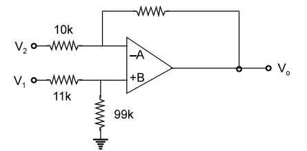
- Expression for the output voltage Vo in terms of the input voltage V1 and V2 in the circuit shown in the figure, assuming operational amplifier to be ideal is Vo = A1 V1 + A2 V2 Values of A1 and A2 would be respectively
-
View Hint View Answer Discuss in Forum
VB = V1 - V1 × 11 = 0.9 V1 110
VA = VB = 0.9 V1Again V0 - VA = VA - V2 100 K 10 K ⇒ V0 - 0.9 V1 = 0.9 V1 - V2 100 10
⇒ V0 = 9.9 V1 – 10 V2
∴ A1 = 9.9 and A2 = – 10Correct Option: B
VB = V1 - V1 × 11 = 0.9 V1 110
VA = VB = 0.9 V1Again V0 - VA = VA - V2 100 K 10 K ⇒ V0 - 0.9 V1 = 0.9 V1 - V2 100 10
⇒ V0 = 9.9 V1 – 10 V2
∴ A1 = 9.9 and A2 = – 10
- An op-amp is open-loop gain of 105 and open-loop upper cut-off frequency of 10 Hz. If this OP-AMP is connected as an amplifier with a closed-loop gain at 100, then new uper cut-off frequency will be
-
View Hint View Answer Discuss in Forum
Upper cut-off frequency at closed loop gain
= fo × (1 + βA) = 10 × 100 = 10 kHzCorrect Option: C
Upper cut-off frequency at closed loop gain
= fo × (1 + βA) = 10 × 100 = 10 kHz
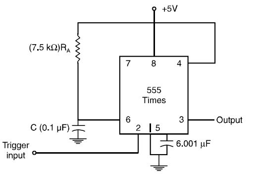
- The period of the output waveform for the circuit of figure shown, when triggered by a negative pulse is
-
View Hint View Answer Discuss in Forum
T = (1.1) RAC
= 1.1(7.5 × 10³) (0.1 × 10– 6) = 0.825 ms.Correct Option: B
T = (1.1) RAC
= 1.1(7.5 × 10³) (0.1 × 10– 6) = 0.825 ms.
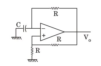
- For the oscillator circuit shown in the given figure, expression for the time period of oscillation can be given by (where t = RC)
-
View Hint View Answer Discuss in Forum
T = 2RC ln 1 + β 1 - β Here , β = 1 = R 2 R + R
∴ T = 2 RC ln 3 = 2 τ ln 3Correct Option: B
T = 2RC ln 1 + β 1 - β Here , β = 1 = R 2 R + R
∴ T = 2 RC ln 3 = 2 τ ln 3

