Digital circuits miscellaneous
- The output of the circuit will be

-
View Hint View Answer Discuss in Forum
NA
Correct Option: D
NA
- The type of gate shown in the given figure is

-
View Hint View Answer Discuss in Forum
NA
Correct Option: D
NA
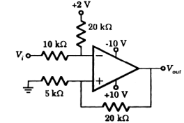
- Schmitt trigger is shown in the figure. The upper and lower threshold voltage are respectively
-
View Hint View Answer Discuss in Forum
Upper crossover voltage when V0 = + 10 V At upper threshold point

5 
(10) = 5 (2) + 20 VTL 5 + 20 10 + 20 10 + 20 ⇒ 2 VTH = 2 - 2 ⇒ VTH = 2V 3 3
Lower crossover voltage when V0 = – 10 V5 (-10) = 10 (2) = 20 VTL 5 + 20 10 + 20 10 + 20
⇒ VTL = – 4VCorrect Option: C
Upper crossover voltage when V0 = + 10 V At upper threshold point
5 (10) = 5 (2) + 20 VTL 5 + 20 10 + 20 10 + 20 ⇒ 2 VTH = 2 - 2 ⇒ VTH = 2V 3 3
Lower crossover voltage when V0 = – 10 V5 (-10) = 10 (2) = 20 VTL 5 + 20 10 + 20 10 + 20
⇒ VTL = – 4V
- A switch-tail ring counter is made by using a single D-FF. The resulting ciruit is
-
View Hint View Answer Discuss in Forum
In a switch– tail ring counter, using D-FF, the complementary output Q is connected to D input for a single D-FF it becomes a T-FF.
Correct Option: D
In a switch– tail ring counter, using D-FF, the complementary output Q is connected to D input for a single D-FF it becomes a T-FF.
- A 4– bit modulo– 16 ripple counter used JK flipflop. If progression delay of each FF is 50 ms, then maximum clock frequency is equal to
-
View Hint View Answer Discuss in Forum
ƒmax = 1 = 1 N:Td 4 × 50 × 10-12
= 5 MHZ.Correct Option: C
ƒmax = 1 = 1 N:Td 4 × 50 × 10-12
= 5 MHZ.

