Analog electronics circuits miscellaneous
- If the input to the ideal comparator shown below is a sinusoidal signal of 8 V (peak to peak) without any DC component, then the output of the comparator has a duty cycle of:

-
View Hint View Answer Discuss in Forum
When i > 2 V, output is positive. When i < 2 V, output is negative, as shown below:
Duty cycle = TON T 5π – π = 6 6 = 1 2π 3 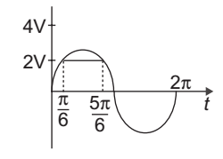
Correct Option: B
When i > 2 V, output is positive. When i < 2 V, output is negative, as shown below:
Duty cycle = TON T 5π – π = 6 6 = 1 2π 3 
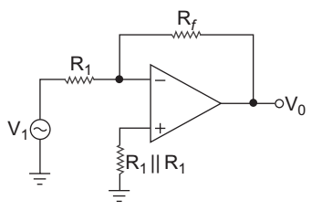
- For the circuit given below will acts as a others inverter if:
-
View Hint View Answer Discuss in Forum
From given circuit
Vo = – Rf . Vi R1
the circuit will act as a phase inverter if
Vo = – Vi, which is possible only when
Rf = R1 VCorrect Option: C
From given circuit
Vo = – Rf . Vi R1
the circuit will act as a phase inverter if
Vo = – Vi, which is possible only when
Rf = R1 V
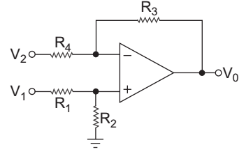
- For the circuit given below CMRR is given by:
-
View Hint View Answer Discuss in Forum
VB = Vi 
R2 
R1 + R2
By using superposition principle.Vo = – R3 . V2 + VB. 1 + R3 R4 R4 or Vo = – R3 . V2 + V1. R2 · R4 + R3 ............(i) R4 R1 + R2 R4
we know,Vc = V1 + V2 .............(ii) 2
Vd = V1 – V2 …(iii)
from equations (ii) and (iii)V1 = Vc + Vd .............(iv) 2 V2 = Vc – Vd .............(v) 2
Substituting these values in equation (i)Vo = – R3 Vc – Vd + Vc + Vd R2 + R4 + R3 R4 2 2 R1 + R2 R4 or Vo = Vc R2 · R4 + R3 - R3 + Vd R2 R4 + R3 R3 ...........(vi) R1 + R2 R4 R4 2 R1 + R2 R4 R4 Since, CMRR = AdM AcM where AdM = Vo |Vd = 0 so from equation (vi) Vd AdM V0 = 1 R2 R4 + R3 + R3 Vd 2 R1 + R2 R4 R4 and AdM = Vo |Vd = 0 Vd AdM = R2 R4 + R3 - R3 R1 + R2 R4 R4
finallyCMRR = 1 
R3(R1 + R2) + R2(R4 + R3) 
2 R3(R1 + R2) - R1(R4 + R3)
Hence alternative (A) is the correct choice.Correct Option: A
VB = Vi R2 R1 + R2
By using superposition principle.Vo = – R3 . V2 + VB. 1 + R3 R4 R4 or Vo = – R3 . V2 + V1. R2 · R4 + R3 ............(i) R4 R1 + R2 R4
we know,Vc = V1 + V2 .............(ii) 2
Vd = V1 – V2 …(iii)
from equations (ii) and (iii)V1 = Vc + Vd .............(iv) 2 V2 = Vc – Vd .............(v) 2
Substituting these values in equation (i)Vo = – R3 Vc – Vd + Vc + Vd R2 + R4 + R3 R4 2 2 R1 + R2 R4 or Vo = Vc R2 · R4 + R3 - R3 + Vd R2 R4 + R3 R3 ...........(vi) R1 + R2 R4 R4 2 R1 + R2 R4 R4 Since, CMRR = AdM AcM where AdM = Vo |Vd = 0 so from equation (vi) Vd AdM V0 = 1 R2 R4 + R3 + R3 Vd 2 R1 + R2 R4 R4 and AdM = Vo |Vd = 0 Vd AdM = R2 R4 + R3 - R3 R1 + R2 R4 R4
finallyCMRR = 1 R3(R1 + R2) + R2(R4 + R3) 2 R3(R1 + R2) - R1(R4 + R3)
Hence alternative (A) is the correct choice.
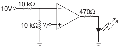
- The LED in the circuit shown below will be on if νi is:
-
View Hint View Answer Discuss in Forum
In the given op-amp circuit is working in open-loop mode, therefore output will be either + Vsat or – Vsat , and in order to glow LED, output voltage must be positive and this can be achieved by making noninverting terminal voltage greater than the inverting terminal voltage.
Inverting terminal voltage is– = 10 (+ 10 V) = + 5 V 10 + 10
Hence i > 5 V
So alternative (C) is the correct choice.Correct Option: C
In the given op-amp circuit is working in open-loop mode, therefore output will be either + Vsat or – Vsat , and in order to glow LED, output voltage must be positive and this can be achieved by making noninverting terminal voltage greater than the inverting terminal voltage.
Inverting terminal voltage is– = 10 (+ 10 V) = + 5 V 10 + 10
Hence i > 5 V
So alternative (C) is the correct choice.
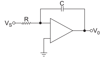
- In the circuit shown, R = 1 MΩ (C = 0.5 µF). Vs is a step voltage of magnitude – 0.5 volt, V0 is given by:
-
View Hint View Answer Discuss in Forum
Output of the integrator,
Vo = – 1 Vi dt RC Vo = – 1 (–0·5)dt 1 × 106 × 0·5 × 10–6
or Vo = + 1. t
or Vo = + t. voltCorrect Option: C
Output of the integrator,
Vo = – 1 Vi dt RC Vo = – 1 (–0·5)dt 1 × 106 × 0·5 × 10–6
or Vo = + 1. t
or Vo = + t. volt

