Analog electronics circuits miscellaneous
Direction: Consider the circuit shown below:

- If Vi = 2 V, then output V0 is:
-
View Hint View Answer Discuss in Forum
Vi = 2V
Vi > 0, then V0 < 0, diode D2 conduct while D1 not conductV0 = – Vi 
Rf 
R1 or V0 = – 2. 6 = – 6 V 2 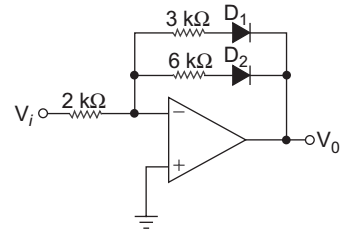
Correct Option: B
Vi = 2V
Vi > 0, then V0 < 0, diode D2 conduct while D1 not conductV0 = – Vi Rf R1 or V0 = – 2. 6 = – 6 V 2 
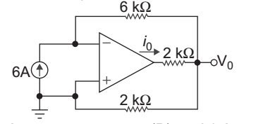
- Calculate value of i0
-
View Hint View Answer Discuss in Forum
KCL at inverting node
6 = 0 – Vo 6
or V0 = – 36
KCL at output nodeV0 + V0 – 0 = io 2 6 or io = 4V0 = 4 × – 36 = – 24 A 6 6 
Correct Option: B
KCL at inverting node
6 = 0 – Vo 6
or V0 = – 36
KCL at output nodeV0 + V0 – 0 = io 2 6 or io = 4V0 = 4 × – 36 = – 24 A 6 6 
- The ideal characteristics of op-amp are:
(i) input impedance, Ri = ∞
(ii) output impedance, R0 = ∞
(iii) bandwidth impedance, BW = 0
(iv) gain impedance, A = ∞ The correct statement are:
-
View Hint View Answer Discuss in Forum
NA
Correct Option: C
NA
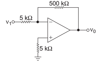
- In the circuit shown below the input offset voltage and input offset current are Vio = 4 mV and Iio = 150 nA. The total output offset voltage is:
-
View Hint View Answer Discuss in Forum
Total output offset voltage is given by relation
VOT = 1 + Rf Vos + Rf. IB R1
where, VOT = total output offset voltage
Rf = feedback resistance
Vos = input offset voltage
IB = input offset current Now,VOT = 1 + 500 4 × 10⁻³ + 5000 × 103 × 150 × 10–9 5
VOT = 404 × 10–3 + 75 × 10–3
or VOT = 479 × 10–3 = 479 mV.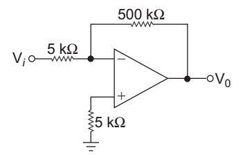
Correct Option: A
Total output offset voltage is given by relation
VOT = 1 + Rf Vos + Rf. IB R1
where, VOT = total output offset voltage
Rf = feedback resistance
Vos = input offset voltage
IB = input offset current Now,VOT = 1 + 500 4 × 10⁻³ + 5000 × 103 × 150 × 10–9 5
VOT = 404 × 10–3 + 75 × 10–3
or VOT = 479 × 10–3 = 479 mV.
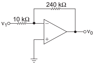
- In the circuit of fig. shown the op-amp slew rate is SR = 0.5 V/µs. If the amplitude of input signal is 0.02 V, then the maximum frequency that may be used is:
-
View Hint View Answer Discuss in Forum
Max. output voltage
Vo = Vi – 240 = 24 × 0.02 10
= 0.48 V
S.R. 2 π fmax. Vmax
or S.R.. Voor S.R. Vo or = 0·5 × 106 = 1.1 × 10⁶ rad/s. 0·48 Correct Option: C
Max. output voltage
Vo = Vi – 240 = 24 × 0.02 10
= 0.48 V
S.R. 2 π fmax. Vmax
or S.R.. Voor S.R. Vo or = 0·5 × 106 = 1.1 × 10⁶ rad/s. 0·48

