Analog electronics circuits miscellaneous
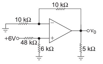
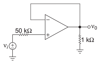
- Find ν0 for the circuit given below:
-
View Hint View Answer Discuss in Forum
NA
Correct Option: A
NA
- For the circuit shown below relation is:

-
View Hint View Answer Discuss in Forum
From op-amp (1) circuit
VA = Vi 
1 + 10 
1
VA = 11 Vi ..........................(i)
from op-amp (2) circuit
Vo1 = – VA = – 11 Vi .....................(ii)
from op-amp (3) circuitVo2 = – VA 5 = – VA 5
= – 11 Vi .....................(iii)
Therefore Vo1 = Vo2
Hence alternative (A) is the correct choice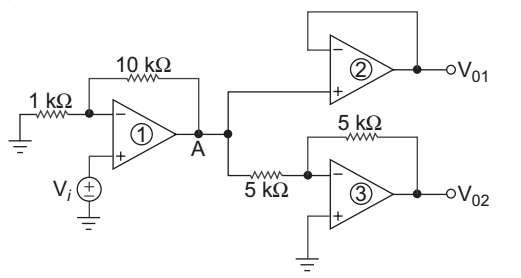
Correct Option: A
From op-amp (1) circuit
VA = Vi 1 + 10 1
VA = 11 Vi ..........................(i)
from op-amp (2) circuit
Vo1 = – VA = – 11 Vi .....................(ii)
from op-amp (3) circuitVo2 = – VA 5 = – VA 5
= – 11 Vi .....................(iii)
Therefore Vo1 = Vo2
Hence alternative (A) is the correct choice
- For the circuit given below:
-
View Hint View Answer Discuss in Forum
Since to avoid loading effect input impedance should be high, and in order to active this Rf should be high also.
Correct Option: C
Since to avoid loading effect input impedance should be high, and in order to active this Rf should be high also.
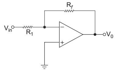
- If open-loop gain is Aod = 999 in the circuit of the closed-loop gain is:
-
View Hint View Answer Discuss in Forum
From given circuit
V– = Vo
V+ = ViAod = Vo = Vo V+ – V– Vi – Vo 999 = Vo Vi – Vo
999 Vi – 999 Vo = Vo
999 Vi = 1000 Voor Vo = 999 = 0.999 Vi 1000 or ACL = Vo = 0.999 Vi Correct Option: B
From given circuit
V– = Vo
V+ = ViAod = Vo = Vo V+ – V– Vi – Vo 999 = Vo Vi – Vo
999 Vi – 999 Vo = Vo
999 Vi = 1000 Voor Vo = 999 = 0.999 Vi 1000 or ACL = Vo = 0.999 Vi
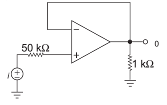
- The circuit is as shown below:
The ideal closed-loop voltage gain is:
-
View Hint View Answer Discuss in Forum
From given circuit
Vo = Vior V0 = 1 Vi 
Correct Option: A
From given circuit
Vo = Vior V0 = 1 Vi