Electrical machines miscellaneous
- A cylindrical rotor generator delivers 0.5 pu power in the steady-state to an infinite bus through a transmission line of reactance 0.5 pu. The generator no-load voltage is 1.5 pu and the infinite bus voltage is 1 pu. The inertia constant of the generator is 5 MW-s/MVA and the generator reactance is 1 pu. The critical clearing angle, in degrees, for a three-phase dead short circuit fault at the generator terminal is
-
View Hint View Answer Discuss in Forum
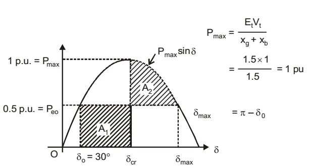
A1 = Accelerating area, δcr = critical clearing angle
A2 = Decelerating area.
Equal area acceleration states that for stability A1 = A2
⇒ Peo(δcr - δo) =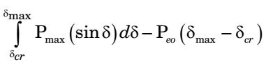
⇒ Peo (δcr - δo) = Pmax(cos δcr - cos δmax) - Peo (δmax - δcr)
⇒ Peo (δcr - δo) + Pmax cos δmax = Pmax cos δcr⇒ cos δcr = Peo (δmax - δo) + cos δmax Pmax δmax = 
π - 30° . π 
rad = 2.61 rad 180°
then, cos δcr = 0.5 (2.61 – 0.52) + cos 150° = 0.179
δcr = cos– 1 0.179 = 79.6°
Correct Option: C
A1 = Accelerating area, δcr = critical clearing angle
A2 = Decelerating area.
Equal area acceleration states that for stability A1 = A2
⇒ Peo(δcr - δo) =
⇒ Peo (δcr - δo) = Pmax(cos δcr - cos δmax) - Peo (δmax - δcr)
⇒ Peo (δcr - δo) + Pmax cos δmax = Pmax cos δcr⇒ cos δcr = Peo (δmax - δo) + cos δmax Pmax δmax = π - 30° . π rad = 2.61 rad 180°
then, cos δcr = 0.5 (2.61 – 0.52) + cos 150° = 0.179
δcr = cos– 1 0.179 = 79.6°
- The figure shows a two-generator system supplying a load of PD = 40 MW, connected at bus 2.
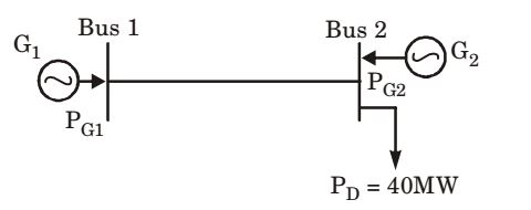
The fuel cost of generators G1 and G2 are :
C1 (PG1) = 10,000 Rs/MWh and C2 (PG2) = 12,500 Rs/MWh
and the loss in the line is Ploss(pu) = 0.5 PG1(pu) 2,
where the loss coefficient is specified in pu on a 100 M VA base. The most economic power generation schedule in MW is
-
View Hint View Answer Discuss in Forum
PL = 0.5 PG12
PL is given by,
PL = B11 PG12 + 2B12 PG1 PG2 + PG22 B22
where B11, B12 & B22 are loss - coefficients.
Since load PD is connected to Bus 2,
B22 = B12 = 0.Now , ∂PL = 2 × 0.5 PG1 = PG1 ∂PG1 and ∂PL = 0 ∂PG2 Penality factors, L1 = 1 = 1 1 - 1 1 - PG1 ∂PG1 and L2 = 1 = 1 1 - 1 ∂PG1
Now, L1 .C1 (PG1) = L2 C2 (PG2) = λ⇒ 1 × 10000 = 1 × (12500) 1 - PG1
⇒ PG1 = 0.2 P.U.
⇒ PG1 = 20 MW
As, PG1 + PG2 = PD + PL = PD + 0.5 PG12
⇒ 20 + PG1 = 40 + 0.5 × (0.2)2 × 100
⇒ PG2 = 22 MW
Correct Option: B
PL = 0.5 PG12
PL is given by,
PL = B11 PG12 + 2B12 PG1 PG2 + PG22 B22
where B11, B12 & B22 are loss - coefficients.
Since load PD is connected to Bus 2,
B22 = B12 = 0.Now , ∂PL = 2 × 0.5 PG1 = PG1 ∂PG1 and ∂PL = 0 ∂PG2 Penality factors, L1 = 1 = 1 1 - 1 1 - PG1 ∂PG1 and L2 = 1 = 1 1 - 1 ∂PG1
Now, L1 .C1 (PG1) = L2 C2 (PG2) = λ⇒ 1 × 10000 = 1 × (12500) 1 - PG1
⇒ PG1 = 0.2 P.U.
⇒ PG1 = 20 MW
As, PG1 + PG2 = PD + PL = PD + 0.5 PG12
⇒ 20 + PG1 = 40 + 0.5 × (0.2)2 × 100
⇒ PG2 = 22 MW
- The slip of an induction motor normally does not depend on
-
View Hint View Answer Discuss in Forum
Slip = Ns - Nr Ns
So depends on Ns (synchronous speed)
So depends on Nr (rotor speed)
If torque increases Nr decreases
It will not dependent on core lossCorrect Option: D
Slip = Ns - Nr Ns
So depends on Ns (synchronous speed)
So depends on Nr (rotor speed)
If torque increases Nr decreases
It will not dependent on core loss
- A 4-pole induction motor, supplied by a slightly unbalanced three-phase 50 Hz source, is rotating at 1440 rpm. The electrical frequency in Hz of the induced negative sequence current in the rotor is
-
View Hint View Answer Discuss in Forum
S = 1500 - 1440 = 0.04 1500
Frequency of +ve seq. current in rotor= 1500 - 1440 × 50 = 0.04 × 50 1500
Frequency of – ve current in rotor= 1500 + 1440 × 50 = 98 Hz 1500
Correct Option: B
S = 1500 - 1440 = 0.04 1500
Frequency of +ve seq. current in rotor= 1500 - 1440 × 50 = 0.04 × 50 1500
Frequency of – ve current in rotor= 1500 + 1440 × 50 = 98 Hz 1500

