Power electronics and drives miscellaneous
- The fully controlled thyristor converter in the given figure is fed from a single-phase source. When the firing angle is 0°, the dc output voltage of the converter is 300 V. What will be the output voltage for a firing angle of 60°, assuming continuous conduction?
-
View Hint View Answer Discuss in Forum

For Fully Controlled Converter (FCC)Average output voltage, V0 = 2 √2 V cos α (V = rms) π
For α = 0, V0 = 300∴ 300 = 2 √2 .V π ⇒ V = 300 π 2 √2 A α = 60 , V0 = 2 √2 
300π 
.cos 60 π 2 √2 = 300 × 1 = 150 V 2 Correct Option: A
For Fully Controlled Converter (FCC)Average output voltage, V0 = 2 √2 V cos α (V = rms) π
For α = 0, V0 = 300∴ 300 = 2 √2 .V π ⇒ V = 300 π 2 √2 A α = 60 , V0 = 2 √2 300π .cos 60 π 2 √2 = 300 × 1 = 150 V 2
- An SCR is considered to be a semi-controlled device because
-
View Hint View Answer Discuss in Forum
NA
Correct Option: C
NA
- The following circuit has a source voltage Vs as shown in the graph. The current through the circuit is also shown.
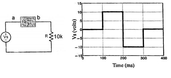

The element connected between a and b could be
-
View Hint View Answer Discuss in Forum
When a forward biased diode is reverse biased, initially it conducts due to the flow of stored charges. After some ti me it goes int o nonconducting state.
Alternately
For 0 < t < 100 ms, Vs = 0,
is = 0; diode not conduct
For 100 < t < 200 ms, Vs = 10V,i = 10 = 1 mA ; diode conducts 10K
For 200 < t < 300 ms, Vs = – 10V, i = 0; diode reverse bias
current is zero after small reverse recovery time.
For 300 < t < 400 ms, Vs = 0;
i = 0; diode not conductCorrect Option: A
When a forward biased diode is reverse biased, initially it conducts due to the flow of stored charges. After some ti me it goes int o nonconducting state.
Alternately
For 0 < t < 100 ms, Vs = 0,
is = 0; diode not conduct
For 100 < t < 200 ms, Vs = 10V,i = 10 = 1 mA ; diode conducts 10K
For 200 < t < 300 ms, Vs = – 10V, i = 0; diode reverse bias
current is zero after small reverse recovery time.
For 300 < t < 400 ms, Vs = 0;
i = 0; diode not conduct
- A three phase fully controlled bridge converter is feeding a load drawing a constant and ripple free load current of 10 A at a firing angle of 30°. The approximate Total Harmonic Distortion (%THD) and the rms value of fundamental component of the input current will respectively be
-
View Hint View Answer Discuss in Forum
Rms value of load current,
Is = Io √2 / 3 = 10 √2 / 3 = 8.165 A
Supply current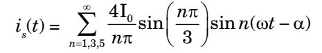
Rms value of fundamental current,is1 = 4π0 sin π = 4 × 10 
√3 
= 7.8 A √2π 3 √2π 2
Then, THD (Total harmonic distortion)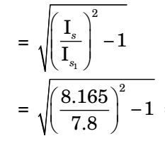
= 0.31 = 31%Correct Option: B
Rms value of load current,
Is = Io √2 / 3 = 10 √2 / 3 = 8.165 A
Supply current
Rms value of fundamental current,is1 = 4π0 sin π = 4 × 10 √3 = 7.8 A √2π 3 √2π 2
Then, THD (Total harmonic distortion)
= 0.31 = 31%
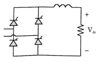
- The power electronic converter shown in the figure given below has a single-pole double-throw switch. The pole P of the switch is connected alternately to throws A and B. The converter shown is a
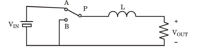
-
View Hint View Answer Discuss in Forum
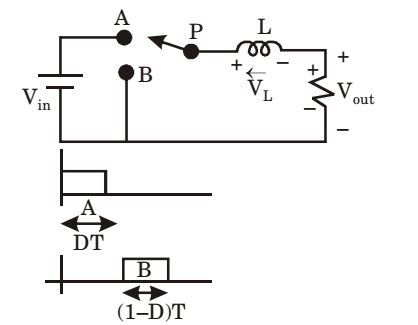
Let Duty cycle be ‘D’.
When at A : t = 0Vin = L di + Vout , (iL)in = (Vin - V0) DT dt L
When at B : At t = DTVout = -VL = -LdiL dt (iL)off = -Vout (1 - D)T L
(Vin – Vout) DT + (– Vout) (1 – D)T = 0
⇒ (Vin – Vout) D = Vout(1 – D)
⇒ Vout = DVin and D < 1
So, step down chopper.
Correct Option: A
Let Duty cycle be ‘D’.
When at A : t = 0Vin = L di + Vout , (iL)in = (Vin - V0) DT dt L
When at B : At t = DTVout = -VL = -LdiL dt (iL)off = -Vout (1 - D)T L
(Vin – Vout) DT + (– Vout) (1 – D)T = 0
⇒ (Vin – Vout) D = Vout(1 – D)
⇒ Vout = DVin and D < 1
So, step down chopper.

