Power electronics and drives miscellaneous
- A 220 V 1400 rpm, 40 A separately excited dc motor has an armature resistance of 0.4Ω. The motor is fed from a single phase circulating current dual converter with an input ac line voltage of 220 V (rms). The approximate firing angles of the dual converter for motoring operation at 50% of rated torque and 1000 rpm will be
-
View Hint View Answer Discuss in Forum
At rated speed and torque, E = V – Ia Ra= 220 – 40 × 0.4 = 204 volts
At 1000 rpm and 50% of rated torque, since
T ∝ II2 = 1 × 40 = 20 A 2 ∴ E2 = E1 × N2 N1 = 204 × 1000 = 145.71 volts 1400
∴ Applied Voltage, V2 = E2 + I 2 R2
= 145.71 + 20 × 0.4 = 153.71 volts
Hence output of converter (rectifier 1),V0 = 2Vm cos α1 = 153.71 π ∴ 2 × √2 × 220 cos α1 = 153.71 π
⇒ α1 = 39.1° ≈ 39°
∴ Firing angle of rectifier, α2 = 180 – α1 = 141°
Hence α1 = 39° and α2 = 141°Correct Option: C
At rated speed and torque, E = V – Ia Ra= 220 – 40 × 0.4 = 204 volts
At 1000 rpm and 50% of rated torque, since
T ∝ II2 = 1 × 40 = 20 A 2 ∴ E2 = E1 × N2 N1 = 204 × 1000 = 145.71 volts 1400
∴ Applied Voltage, V2 = E2 + I 2 R2
= 145.71 + 20 × 0.4 = 153.71 volts
Hence output of converter (rectifier 1),V0 = 2Vm cos α1 = 153.71 π ∴ 2 × √2 × 220 cos α1 = 153.71 π
⇒ α1 = 39.1° ≈ 39°
∴ Firing angle of rectifier, α2 = 180 – α1 = 141°
Hence α1 = 39° and α2 = 141°
- In the voltage doubler circuit shown in the figure, the switch ‘S’ is closed at t = 0. Assuming diodes D1 and D2 to be ideal, load resistance to be infinite and initial capacitor voltages to be zero, the steady state voltage across capacitors C1 and C2 will be

-
View Hint View Answer Discuss in Forum
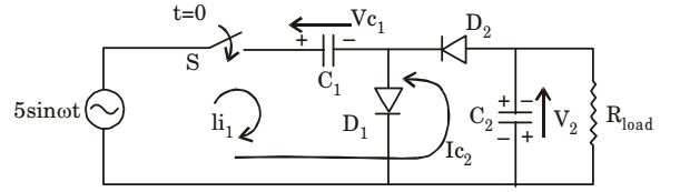
First capacitor C1 will charge through diode D1 upto Vmax (5 V) with shown polarity
∴ VC1 = 5 V
Now, diode D1 will be reverse biased and D2 will be forward biased and capacitor C2 will charge in reverse direction through diode D2 upto 2Vmax
∴ VC2Hence, VC1 = 5 V1, VC2 = 10 VCorrect Option: C
First capacitor C1 will charge through diode D1 upto Vmax (5 V) with shown polarity
∴ VC1 = 5 V
Now, diode D1 will be reverse biased and D2 will be forward biased and capacitor C2 will charge in reverse direction through diode D2 upto 2Vmax
∴ VC2Hence, VC1 = 5 V1, VC2 = 10 V
- A 3-phase Voltage Source Inverter is operated in 180° conduction mode. Which one of the following statements is true?
-
View Hint View Answer Discuss in Forum
Line voltage,

For n = 3, VL = 0. as cos 
nπ 
= 0 6
Pole voltage,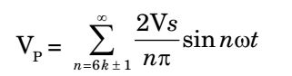
For n = 3, VP ≠ 0.
Hence it is not free from third hormonics.Correct Option: B
Line voltage,
For n = 3, VL = 0. as cos nπ = 0 6
Pole voltage,
For n = 3, VP ≠ 0.
Hence it is not free from third hormonics.
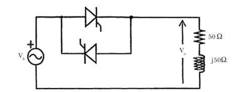
- In the single phase voltage controller circuit shown in the figure given below, for what range of triggering angle (α), the output voltage (v0) is not controllable?
-
View Hint View Answer Discuss in Forum
R + jXL = (50 + j 50) Ω
∴ tan φ = ω L = XL = 50 = 1 R R 50
⇒ φ = 45°
Hence firing angle α must be greater than 45° Thus for 0 < α < 45°, VO is uncontrollable.
Correct Option: A
R + jXL = (50 + j 50) Ω
∴ tan φ = ω L = XL = 50 = 1 R R 50
⇒ φ = 45°
Hence firing angle α must be greater than 45° Thus for 0 < α < 45°, VO is uncontrollable.
- The equivalent circuits of a diode, during forward biased and reverse biased conditions, are shown in the figure given below.
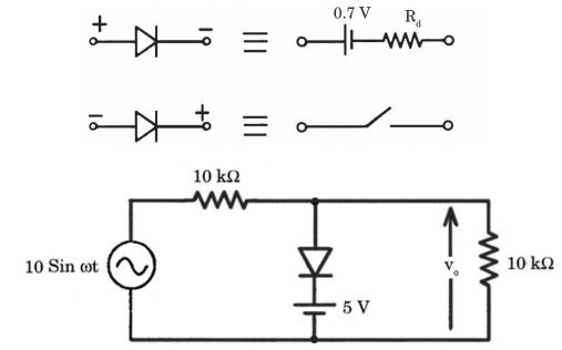
If such a diodes is used in clipper circuit of figure given above, the output voltage (v0) of the circuit will be
-
View Hint View Answer Discuss in Forum
During +ve cycle of input voltage, Vi,
When Vi > 5.7 volts
Diode becomes forward-biased and the circuit will be as shown here
Rf is the diode forward resistance.
Output voltage, V0 = 5.7 + RfI
During – ve cycle of input voltage Vi, Diode D is reversed-biased and cut-off.
The circuit will be as shown below.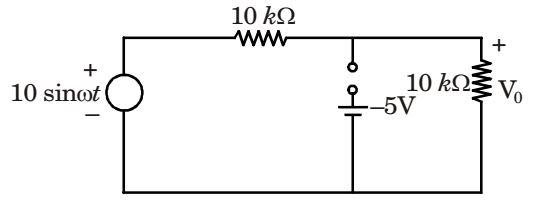
V0 = 10 sinωt . 10 kΩ = 5 sinωt 10 kΩ + 10 kΩ
Correct Option: A
During +ve cycle of input voltage, Vi,
When Vi > 5.7 volts
Diode becomes forward-biased and the circuit will be as shown here
Rf is the diode forward resistance.
Output voltage, V0 = 5.7 + RfI
During – ve cycle of input voltage Vi, Diode D is reversed-biased and cut-off.
The circuit will be as shown below.V0 = 10 sinωt . 10 kΩ = 5 sinωt 10 kΩ + 10 kΩ

