Power electronics and drives miscellaneous
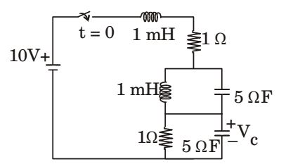
- In the circuit shown in the figure, the switch is closed at time t = 0. The steady state value of the voltage Vc is ______V.
-
View Hint View Answer Discuss in Forum
NA
Correct Option: C
NA
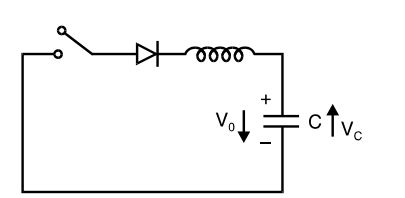
- In the figure, if C = 8 F and L = 0.2 mH and V0 = 200V, then peak current through diode is given by ______ A.
-
View Hint View Answer Discuss in Forum

Correct Option: A
- The average on-state current for an SCR is 20 A for a conduction angle of 120°. The average on state current for 60° conduction angle will be ______A .
-
View Hint View Answer Discuss in Forum
Iav = Im form factor
where, form factor for 120° = 1.878 and form factor for 60° = 2.7781
So, Iav is less than 20 ACorrect Option: B
Iav = Im form factor
where, form factor for 120° = 1.878 and form factor for 60° = 2.7781
So, Iav is less than 20 A
- In the figure, switch S is closed at t = 0 with iL (0) = 0 and VC (0) = 0. In steady state VC equals ______ .

-
View Hint View Answer Discuss in Forum
At t = 0, iL (0) = 0, VC(0) = 0
∴ VD = 100 V
But at steady-state inductor is short circuited, therefore
VC = 100 – (+100) = 0 VCorrect Option: A
At t = 0, iL (0) = 0, VC(0) = 0
∴ VD = 100 V
But at steady-state inductor is short circuited, therefore
VC = 100 – (+100) = 0 V
- A single-phase full-bridge voltage source inverter feeds a purely inductive load, as shown in the given figure, where T1, T2, T3, T4 are power transistors and D1, D2, D3, D4 are feedback diodes. The inverter is operated in square-wave mode with a frequency of 50 Hz. If average load current is zero, what is the time duration of conduction of each feedback diode in a cycle?

-
View Hint View Answer Discuss in Forum
NA
Correct Option: D
NA

