Power electronics and drives miscellaneous
- A single-phase voltage source inverter shown in figure is feeding power to a load. The triggering pulses of the devices are also shown in the figure.

If the load current is sinusoidal and is zero at 0, π, 2π...., the node voltage VAO has the waveform
-
View Hint View Answer Discuss in Forum
NA
Correct Option: D
NA
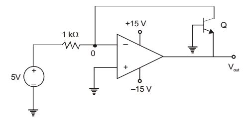
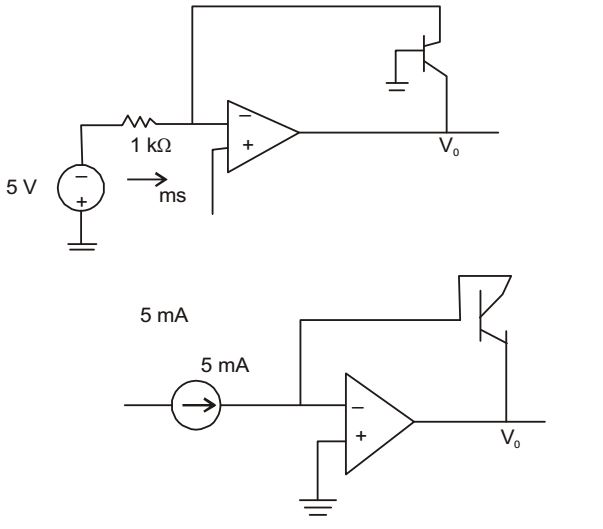
- In the circuit shown below what is the output voltage (Vout) in Volts if a silicon transistor Q and an ideal op-amp are used?
-
View Hint View Answer Discuss in Forum
I = I, e I = I0e VRE / VT , I = I0e -V0 / VT-V0 = VT 
ln I 
= VT ln I3ms I0 Is
V0 = - 0.7
RL = √Rs² + Xs² = √4² + 3² = 5Correct Option: B
I = I, e I = I0e VRE / VT , I = I0e -V0 / VT-V0 = VT ln I = VT ln I3ms I0 Is
V0 = - 0.7
RL = √Rs² + Xs² = √4² + 3² = 5
- In the feedback network shown below, if the feedback factor k is increased, then the

-
View Hint View Answer Discuss in Forum
Input Independence of a voltage-voltage feedback circuit = Zi (1 + A0 k)
Zi = initial input impedance (without feed output
Impedance of a voltage-voltage feedback circuit = Z0 / (1 + A0 k)
Z0 = initial output impedance (without feedback)
Hence, As K is increased, the input impedance will increase and output impedance will decrease.
Correct Option: A
Input Independence of a voltage-voltage feedback circuit = Zi (1 + A0 k)
Zi = initial input impedance (without feed output
Impedance of a voltage-voltage feedback circuit = Z0 / (1 + A0 k)
Z0 = initial output impedance (without feedback)
Hence, As K is increased, the input impedance will increase and output impedance will decrease.
- In the circuit shown below, the knee current of the ideal Zener diode is 10 mA. To maintain 5 V across RL, the minimum value of RL in Ω and the minimum power rating of the Zener diode in mW respectively are

-
View Hint View Answer Discuss in Forum
Is = Iz + IL
Is – Iz = IL
Two extreme condition :
If Iz (min),then IL (max)
If Iz (max) then IL (min) = 0Iz (max) = Is = 10 - 5 = 50 mA 10
Iz (min) = Is – IL (max)
IL (max) = Is – Iz (min) = Is – Iz = (50 – 10) = 40mARL (min) = V = 5 K = 125 Ω IL (max) 40
Pz = Vz × Iz (max) = 5 × 50 mA = 250 mwCorrect Option: B
Is = Iz + IL
Is – Iz = IL
Two extreme condition :
If Iz (min),then IL (max)
If Iz (max) then IL (min) = 0Iz (max) = Is = 10 - 5 = 50 mA 10
Iz (min) = Is – IL (max)
IL (max) = Is – Iz (min) = Is – Iz = (50 – 10) = 40mARL (min) = V = 5 K = 125 Ω IL (max) 40
Pz = Vz × Iz (max) = 5 × 50 mA = 250 mw
- The average power delivered to an impedance (4 – j3) Ω by a current 5 cos (100 πt + 100) A is
-
View Hint View Answer Discuss in Forum
Z = 4 – j3 = RL – jXC; RL = 4;
I = 5 cos (100πt + 100) = Im cos2 (ωt + α)P = 1 Im2 .RL = 1 × 52 × 4 = 50 W 2 2 Correct Option: B
Z = 4 – j3 = RL – jXC; RL = 4;
I = 5 cos (100πt + 100) = Im cos2 (ωt + α)P = 1 Im2 .RL = 1 × 52 × 4 = 50 W 2 2

