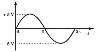
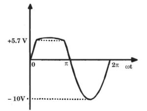
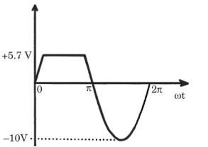
-
The equivalent circuits of a diode, during forward biased and reverse biased conditions, are shown in the figure given below.
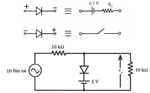
If such a diodes is used in clipper circuit of figure given above, the output voltage (v0) of the circuit will be
Correct Option: A
During +ve cycle of input voltage, Vi,
When Vi > 5.7 volts
Diode becomes forward-biased and the circuit will be as shown here
Rf is the diode forward resistance.
Output voltage, V0 = 5.7 + RfI
During – ve cycle of input voltage Vi, Diode D is reversed-biased and cut-off.
The circuit will be as shown below.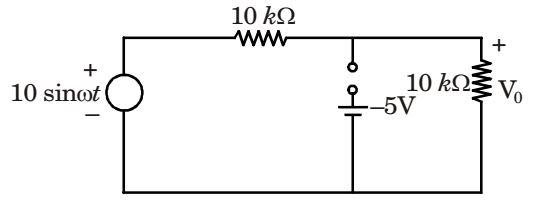
| V0 = 10 sinωt . | = 5 sinωt | |
| 10 kΩ + 10 kΩ |
