Network theory miscellaneous
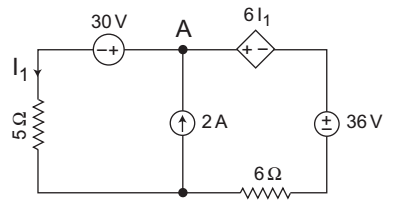
- For the circuit shown below, the value of I1 = ?
-
View Hint View Answer Discuss in Forum
The given circuit:
Applying KCL at node A, we getVA - 30 + VA - 36 - 6 l1 = 2 . . . . . . .(i) 5 6 l1 = VA - 30 5
VA = 5 l1 + 30 . . . . . . . . . . (ii)
From equation (i) and (ii), we getVA 1 + 1 - l1 = 14 5 6 (5I1 + 30) 6 + 5 - l1 = 14 30
or
55 I1 + 330 – 30 I1 = 420
or
25 I1 = 420 – 330 = 90
or
I1 = 90/25 = 18/5 = 3·6
Hence alternative (C) is the correct choice.Correct Option: C
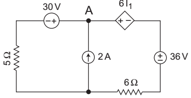
The given circuit:
Applying KCL at node A, we getVA - 30 + VA - 36 - 6 l1 = 2 . . . . . . .(i) 5 6 l1 = VA - 30 5
VA = 5 l1 + 30 . . . . . . . . . . (ii)
From equation (i) and (ii), we getVA 1 + 1 - l1 = 14 5 6 (5I1 + 30) 6 + 5 - l1 = 14 30
or
55 I1 + 330 – 30 I1 = 420
or
25 I1 = 420 – 330 = 90
or
I1 = 90/25 = 18/5 = 3·6
Hence alternative (C) is the correct choice.
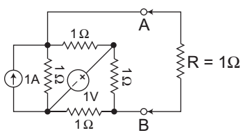
- If a resistance R of 1Ω is connected across the terminals AB as shown in the given figure then the current flowing through R will be—
-
View Hint View Answer Discuss in Forum
The given circuit
Given, RL = R = 1Ω
Equivalent circuit for calculation of Rth is shown below: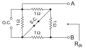
From figure, Rth = (1|| 1) + (1||1) = 1/2 + 1/2 = 1Ω
Equivalent circuit for calculation of Vth is shown below:
Applying KVL in the loop 1, we get
– I1 × 1 + 1 – I1 × 1 – 1 = 0
or
I1 = 0
Again, applying KVL in the loop 2, we get
1 – I2 × 1 – I2 × 1=0
or
I2 = 1/2 A
Now, Vth = 1 × I1 + 1 × I2 = 1 × 0 + 1 × 1/2 = 1/2 V
Now,I2 = Vth 6 + 5 = 0.5 = 0.5 = 0.25A Rth + RL 1 + 1 2
Hence alternative (C) is the correct choice.Correct Option: C
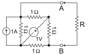
The given circuit
Given, RL = R = 1Ω
Equivalent circuit for calculation of Rth is shown below:
From figure, Rth = (1|| 1) + (1||1) = 1/2 + 1/2 = 1Ω
Equivalent circuit for calculation of Vth is shown below:
Applying KVL in the loop 1, we get
– I1 × 1 + 1 – I1 × 1 – 1 = 0
or
I1 = 0
Again, applying KVL in the loop 2, we get
1 – I2 × 1 – I2 × 1=0
or
I2 = 1/2 A
Now, Vth = 1 × I1 + 1 × I2 = 1 × 0 + 1 × 1/2 = 1/2 V
Now,I2 = Vth 6 + 5 = 0.5 = 0.5 = 0.25A Rth + RL 1 + 1 2
Hence alternative (C) is the correct choice.
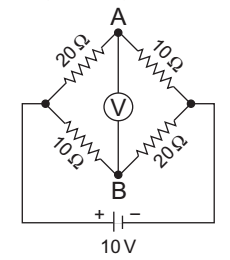
- The reading of high impedance voltmeter V in the bridge circuit shown in the given figure—
-
View Hint View Answer Discuss in Forum
The given circuit:
Voltage at terminal AVA = 10 × 10 = 10 V 10 + 20 3
Voltage at terminal BVB = 10 × 20 = 20 V 20 + 10 3
Now,
VBA = reading of voltmeter= 20 = 10 = 10 = 3.33V 3 3 3 Correct Option: B
The given circuit:
Voltage at terminal AVA = 10 × 10 = 10 V 10 + 20 3
Voltage at terminal BVB = 10 × 20 = 20 V 20 + 10 3
Now,
VBA = reading of voltmeter= 20 = 10 = 10 = 3.33V 3 3 3
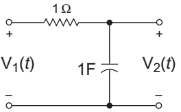
- For the following circuit, a source of V1(t) = e– 2t is applied. What will be the V2 (t)—
-
View Hint View Answer Discuss in Forum
The given circuit
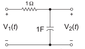
From figureV2(s) = V1(s) 1 = V1(s) s 1 + 1 s = V1(s) s (1 + s)
where,= V1(s) 1 s + 2
[Given V1(t) = e–2t]
Now,V2 (s) = 1 × s = A + B (s + 2) (s + 1) s + 1 s + 2 = - 1 + 2 s + 1 s + 2
or
V2(t) = 2e–2t – e–t
Hence alternative (A) is the correct choice.Correct Option: A
The given circuit
From figureV2(s) = V1(s) 1 = V1(s) s 1 + 1 s = V1(s) s (1 + s)
where,= V1(s) 1 s + 2
[Given V1(t) = e–2t]
Now,V2 (s) = 1 × s = A + B (s + 2) (s + 1) s + 1 s + 2 = - 1 + 2 s + 1 s + 2
or
V2(t) = 2e–2t – e–t
Hence alternative (A) is the correct choice.
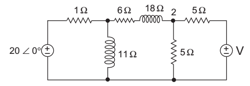
- For the circuit shown below, if the power dissipated in the 6Ω resistor is zero then V is—
-
View Hint View Answer Discuss in Forum
The given circuit:
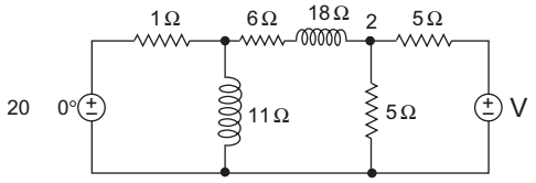
Given that power dissipated in the 6Ω resistor is zero, it means voltage at node 1 is same as 2 (i.e., V1 = V2)
KCL at node 1V1 - 20 0° + V1 + V1 + V2 = 0 1 j1 6 + j8
orV1 1 + 1 20 0°(since V1 = V2) j1
orV1 = 20 0° j .........…(i) (j + 1)
Again KCL at node 2:V2 – V1 + V1 + V2 – V = 0 6 + j8 5 5
or2V2 = V (since V1 = V2) 5 5
orV2 = V ...........(ii) 2
From equation (i) and (ii)20 0° j = V j + 1 2
orV = 2 × 20 0° × 90° 2 × 45°
20 2 45°
Hence alternative (A) is the correct choice.Correct Option: C
The given circuit:
Given that power dissipated in the 6Ω resistor is zero, it means voltage at node 1 is same as 2 (i.e., V1 = V2)
KCL at node 1V1 - 20 0° + V1 + V1 + V2 = 0 1 j1 6 + j8
orV1 1 + 1 20 0°(since V1 = V2) j1
orV1 = 20 0° j .........…(i) (j + 1)
Again KCL at node 2:V2 – V1 + V1 + V2 – V = 0 6 + j8 5 5
or2V2 = V (since V1 = V2) 5 5
orV2 = V ...........(ii) 2
From equation (i) and (ii)20 0° j = V j + 1 2
orV = 2 × 20 0° × 90° 2 × 45°
20 2 45°
Hence alternative (A) is the correct choice.

