Electronic measurements and instrumentation miscellaneous
- A 0–25A ammeter has a guaranteed accuracy of 1 per cent of full scale reading. The current measured by this instrument is 5A. The limiting error in percentage will be:
-
View Hint View Answer Discuss in Forum
Given ammeter range 0 – 25A
relative error = Er = 1% = 0·01
The magnitude of limiting error of the instrument
δA = Er × A where, A is the true value
= 0·01 × 25
= 0·25A
The magnitude of the current being measured is 5.
The relative error at this current isEr = δA = 0.25 = 0.05 A 5
or
percentage relative or limiting error = 5%.Correct Option: B
Given ammeter range 0 – 25A
relative error = Er = 1% = 0·01
The magnitude of limiting error of the instrument
δA = Er × A where, A is the true value
= 0·01 × 25
= 0·25A
The magnitude of the current being measured is 5.
The relative error at this current isEr = δA = 0.25 = 0.05 A 5
or
percentage relative or limiting error = 5%.
- As compared to other voltmeters the digital voltmeter offer the advantage of:
-
View Hint View Answer Discuss in Forum
As compared to other voltmeter the digital voltmeter offers the advantage of:
● Greater speed
● Higher accuracy and resolution
● Less human errorCorrect Option: D
As compared to other voltmeter the digital voltmeter offers the advantage of:
● Greater speed
● Higher accuracy and resolution
● Less human error
- Which of the following conditions are to be satisfied in the figure shown, so that the common variable shaft of resistance R1 and R2 can be graduated in frequency to measure the frequency of E under balanced condition?
1. R1 = R3
2. C1 = C3
3. R2 = 2 R4
4. R2 = R4
Select the correct answer using the codes given below: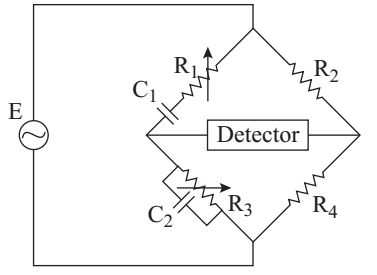
-
View Hint View Answer Discuss in Forum
Under the balanced condition.
From above figure
R1 + 1 
/ 2 = R3 1/jωC3 × 1 1/jωC1 R1 +(1/jωC3) R3
orR4 R1 + 1 = R2 R3 jωC1 jR3ωC3+1
or R4 [jR1ωC1+1] [1 + jωC3R3]=jωC1R2R3
on comparing real and imaginary part, we get,R1R3C2ω = 1 c1ω
orω2 = 1 C1C3R1R3
orω = 1 √C1C3R1R3
If C1 = C3
and R1 = R3
then given R2 = 2R4
Thus condition to be satisfied are
C1 = C3, R1 = R3
and R2 = 2R4
Correct Option: D
Under the balanced condition.
From above figureR1 + 1 / 2 = R3 1/jωC3 × 1 1/jωC1 R1 +(1/jωC3) R3
orR4 R1 + 1 = R2 R3 jωC1 jR3ωC3+1
or R4 [jR1ωC1+1] [1 + jωC3R3]=jωC1R2R3
on comparing real and imaginary part, we get,R1R3C2ω = 1 c1ω
orω2 = 1 C1C3R1R3
orω = 1 √C1C3R1R3
If C1 = C3
and R1 = R3
then given R2 = 2R4
Thus condition to be satisfied are
C1 = C3, R1 = R3
and R2 = 2R4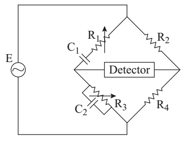
- Match List-I with List-II and select the correct answer using the codes given below the Lists:
List-I List-II A. Meggar 1. Measurement of loss angle in a dielectric. B. Spectrum analyzer 2. Measurement of frequency. C. Schering bridge 3. Measurement of insulation resistance. D. Digital counter 4. Measurement of harmonics.
-
View Hint View Answer Discuss in Forum
● Meggar → Measurement of insulation resistance
● Spectrum analyzer → Measurement of harmonics
● Schering bridge → Measurement of loss angle in a dielectric
● Digital counter → Measurement of frequencyCorrect Option: D
● Meggar → Measurement of insulation resistance
● Spectrum analyzer → Measurement of harmonics
● Schering bridge → Measurement of loss angle in a dielectric
● Digital counter → Measurement of frequency
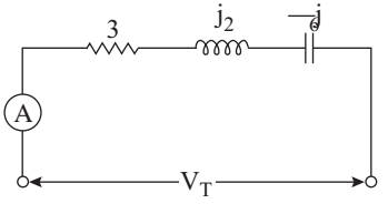
- In the ac circuit shown in the given figure, when the ammeter reads 10A, the readings on a voltmeter placed across the entire circuit and then across each element are given below. Match List-I (Position of the voltmeter) with List-II (readings on the voltmeter) and select the correct answer using the codes given below the list:
List-I List-II A. VT 1. 60 B. VR 2. 20 C. VL 3. 30 D. VC 4. 50 5. 110
A B C D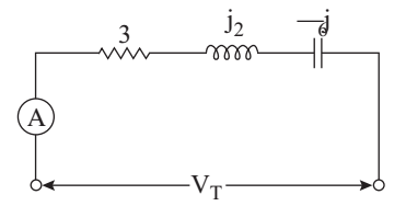
-
View Hint View Answer Discuss in Forum
Given, I = 10A
R = 3Ω
XL = j2Ω
XC = – j6Ω
VR = IR = 10 × 3 = 30V
VL = IXL = 10 × 2 = 20V
VC = IXC = 10 × 6 = 60V
VT = √VR2 + (VL ~ VC)2
or
VT = √302 + (60 – 20)2
or
VT = √302 + 402
or
VT = 50
Finally →VT = 50V VR = 30V VL = 20V Vc = 60V 
Correct Option: D
Given, I = 10A
R = 3Ω
XL = j2Ω
XC = – j6Ω
VR = IR = 10 × 3 = 30V
VL = IXL = 10 × 2 = 20V
VC = IXC = 10 × 6 = 60V
VT = √VR2 + (VL ~ VC)2
or
VT = √302 + (60 – 20)2
or
VT = √302 + 402
or
VT = 50
Finally →VT = 50V VR = 30V VL = 20V Vc = 60V