Power systems miscellaneous
- A 3-phase transmission line is shown in the figure. Voltage drop across the transmission line is given by the following equation:
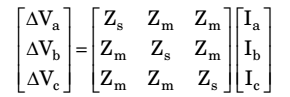
Shunt capacitance of the line can be neglected. If the line has positive sequence impedance of 15 Ω and zero sequence impedance of 48 Ω, then the values of Zs and Zm will be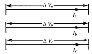
-
View Hint View Answer Discuss in Forum
For the given system, the relationship between sequence impedance and Zs, Zm is given by Positive sequence impedance,
Z1 = Zs – Zm .
Negative sequence impedance,
Z2 = Zs – Zm .
Zero sequence impedance,
Z0 = Zs – 2Zm .
Given Zs – Zm = 15
and Zs + 2Zm = 48
Solving, we get,
Zs = 26, Zm = 11Correct Option: B
For the given system, the relationship between sequence impedance and Zs, Zm is given by Positive sequence impedance,
Z1 = Zs – Zm .
Negative sequence impedance,
Z2 = Zs – Zm .
Zero sequence impedance,
Z0 = Zs – 2Zm .
Given Zs – Zm = 15
and Zs + 2Zm = 48
Solving, we get,
Zs = 26, Zm = 11
- A lossless power system has to serve a load of 250 MW. There are two generators (G1 and G2) in the system with cost curves C1 and C2 respectively defined as follows:
C1 (PG1) = PG1 + 0.055 × PG1²
C2 (PG2) = 3PG2 + 0.03 × PG2²
where PG1 and PG2 are the MW injections from generator G1 and G2 respectively. Then the minimum cost dispatch will be
-
View Hint View Answer Discuss in Forum
C1 (PG1) = PG1 + 0.055 × PG1²
∴ dC1 = 1 + 0.11PG1 dPG1
C2 (PG2) = PG2 + 0.03 × PG2²∴ dC2 = 3 + 0.06 PG2 dPG2
For minimum cost analysisdC1 = dC2 dPG1 dPG2
⇒ 1 + 0.11 PG1 = 3 + 0.006 PG2
or 0.11 PG1 – 0.06 PG2 = 2 ...(1)
and PG1 + PG2 = 250 MW ...(2)
Solving equations (1) and (2), we get
PG1 = 100 MW and PG2 = 150 MWCorrect Option: C
C1 (PG1) = PG1 + 0.055 × PG1²
∴ dC1 = 1 + 0.11PG1 dPG1
C2 (PG2) = PG2 + 0.03 × PG2²∴ dC2 = 3 + 0.06 PG2 dPG2
For minimum cost analysisdC1 = dC2 dPG1 dPG2
⇒ 1 + 0.11 PG1 = 3 + 0.006 PG2
or 0.11 PG1 – 0.06 PG2 = 2 ...(1)
and PG1 + PG2 = 250 MW ...(2)
Solving equations (1) and (2), we get
PG1 = 100 MW and PG2 = 150 MW
- Consider a bundled conductor of an overhead line, consisting of three identical sub-conductors placed at the corners of an equilateral triangle as shown in the figure. If we neglect the charges on the other phase conductors and ground, and assume that spacing between sub-conductors is much larger than their radius, the maximum electric field intensity is experienced at

-
View Hint View Answer Discuss in Forum
Electric field intensity at various points are shown as fallows:
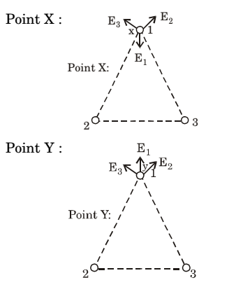

It is clear from the above diagrams that minimum cancellation of vectors occurs at the point Y, hence maximum electric field intensity.Correct Option: B
Electric field intensity at various points are shown as fallows:
It is clear from the above diagrams that minimum cancellation of vectors occurs at the point Y, hence maximum electric field intensity.
- A three phase balanced star connected voltage source with frequency ωrad/s is connected to a star connected balanced load which is purely inductive. The instantaneous line currents and phase to neutral voltages are denoted by (ia, ib, ic) and (van, vbn, vcn) respectively and their rms values are denoted by V and I.
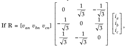
then magnitude of R is
-
View Hint View Answer Discuss in Forum
Assume van as reference phasor,
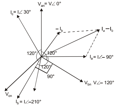
Van = V∠0°
Vbn = V – 120°
Vcn = V ∠120°
As load is purely inductive, Ia lags Van by 90°,
Ib lags Vbn by 90° and Ic lags Van by 90° as shown in the phasor-diagram
Iab = Ia - Ib = I∠-90° - 210° = √3I ∠-60°
Ibc = Ib - Ic = I∠- 210° - I∠30° = √3I ∠-180°
Ica = Ic - Ia = I∠30° - I = ∠- 90° = √3I ∠60°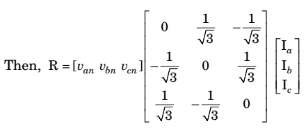
= 1 [VanIbc + VbnIca + VcnIab] √3 = 1 √3I[V∠180° + V∠60° + V∠60°] = 0 √3
Correct Option: A
Assume van as reference phasor,
Van = V∠0°
Vbn = V – 120°
Vcn = V ∠120°
As load is purely inductive, Ia lags Van by 90°,
Ib lags Vbn by 90° and Ic lags Van by 90° as shown in the phasor-diagram
Iab = Ia - Ib = I∠-90° - 210° = √3I ∠-60°
Ibc = Ib - Ic = I∠- 210° - I∠30° = √3I ∠-180°
Ica = Ic - Ia = I∠30° - I = ∠- 90° = √3I ∠60°= 1 [VanIbc + VbnIca + VcnIab] √3 = 1 √3I[V∠180° + V∠60° + V∠60°] = 0 √3

