Network theory miscellaneous
- The time constant for the given circuit will be—

-
View Hint View Answer Discuss in Forum
The given circuit:

The equivalent circuit for calculating time constant is shown below:
Now, time constant,τ = Req Ceq = 6 × 2 = 4sec 3
Hence alternative (C) is the correct choice.Correct Option: C
The given circuit:
The equivalent circuit for calculating time constant is shown below:
Now, time constant,τ = Req Ceq = 6 × 2 = 4sec 3
Hence alternative (C) is the correct choice.
- The voltage V for the network shown below is—

-
View Hint View Answer Discuss in Forum
The given network:
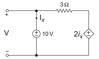
The voltage V for the above network is always equal to 10V.Correct Option: A
The given network:
The voltage V for the above network is always equal to 10V.
- The circuit shown in the figure above—

-
View Hint View Answer Discuss in Forum
The given circuit:
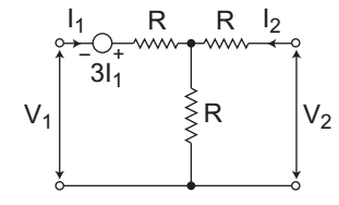
Applying KVL in the input side, we get
V1 + 3I1 + I1R + (I1 + I2) R = 0
or
V1 = I1 (2R – 3) + I2R . . .. .…(i)
Again applying KVL in the output side
V2 = I2R + (I1 + I2)R
or
V2 = I1R + I2.2R …. . . . .(ii)
From equation (i) and (ii)
Z11 = 2R – 3, Z12 = R
Z21 = R, Z22 = 2R
● For the network to be symmetric
Z11 = Z22 (But here Z11 = 2R – 3 and Z22 = 2R)
So, network is not symmetric.
● For the network to be reciprocal:
Z12 = Z21 (Here Z12 = Z21 = R)
So, network is reciprocal.
Thus, we conclude that the given network is reciprocal but not symmetric.Correct Option: A
The given circuit:
Applying KVL in the input side, we get
V1 + 3I1 + I1R + (I1 + I2) R = 0
or
V1 = I1 (2R – 3) + I2R . . .. .…(i)
Again applying KVL in the output side
V2 = I2R + (I1 + I2)R
or
V2 = I1R + I2.2R …. . . . .(ii)
From equation (i) and (ii)
Z11 = 2R – 3, Z12 = R
Z21 = R, Z22 = 2R
● For the network to be symmetric
Z11 = Z22 (But here Z11 = 2R – 3 and Z22 = 2R)
So, network is not symmetric.
● For the network to be reciprocal:
Z12 = Z21 (Here Z12 = Z21 = R)
So, network is reciprocal.
Thus, we conclude that the given network is reciprocal but not symmetric.
- The phasor combination of resistive power and reactive power is called—
-
View Hint View Answer Discuss in Forum
The phasor combination of resistive power and reactive power is called apparent power.
Correct Option: B
The phasor combination of resistive power and reactive power is called apparent power.
- Norton’s current in the circuit shown below is—

-
View Hint View Answer Discuss in Forum
The given circuit
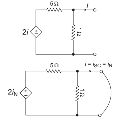
From figure
2iN – 5iN = 0
or
iN = 0ACorrect Option: B
The given circuit
From figure
2iN – 5iN = 0
or
iN = 0A

